BM/BMS Series Hardware Manual
Introduction
www.aerotech.com 1-19
1.6.2. Connector Pin Assignments
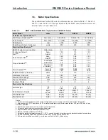
This section contains the pin assignment for the MS motor connector (Table 1-15), MS
feedback connector (Table 1-16), and the optional resolver MS connector (Table 1-17) as
well the D-sub motor and feedback connector (Table 1-18)
Table 1-15:
Motor Power Connector Pin Assignment (MS3101A-10P)
Pin Function
A
Motor Phase A
B
Motor Phase B
C
Motor Phase C
D
Motor Frame Ground
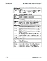
Table 1-16:
Feedback Connector Pin Assignment (MS3101A-20-29P)
Pin Function
Pin
Function
A
Cosine
L
Hall Effect A-N (optional) **
B
Cosine-N
M
Hall Effect B
C
Sine
N
Hall Effect B-N (optional) **
D
Sine-N
P
Hall Effect C
E
Marker
R
Hall Effect C-N (optional) **
F
Marker-N
S
Brake + (optional)*
G
Common
T
Brake – (optional)*
H +5V
J
Shield (no connection
to frame)
K
Hall Effect A
* 24 VDC @ 1 A max
** Not used on BMS280, BMS465 or with an AS encoder
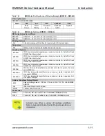
Table 1-17:
Resolver Connector Pin Assignment (MS3101A-20-29P)
Pin Function
Pin
Function
A Sine
+
L
B
Sine –
M
C
N
Sine Shield (no connection to frame)
D
Cosine –
P
Cosine Shield (no connection to frame)
E
Ref +
R
Reference Shield (no connection to frame)
F
Ref –
S
Brake + (optional)*
G
T
Brake – (optional)*
H
J
K
* 24 VDC @ 1 A max
Summary of Contents for BM Series
Page 6: ...Table of Contents BM BMS Series Hardware Manual iv www aerotech com...
Page 8: ...List of Figures BM BMS Series Hardware Manual vi www aerotech com...
Page 10: ...List of Tables BM BMS Series Hardware Manual viii www aerotech com...
Page 12: ...Declaration of Conformity BM BMS Series Hardware Manual x www aerotech com...
Page 50: ...Appendix A BM BMS Series Hardware Manual A 8 www aerotech com...
Page 56: ...Index BM BMS Series Hardware Manual Index 2 www aerotech com...
Page 58: ......

