BM/BMS Series Hardware Manual
List of Figures
www.aerotech.com v
LIST OF FIGURES
Figure 1-1:
BM Series Brushless Motors.....................................................1-1
Figure 1-2:
Hall Effect and Motor Phasing ..................................................1-3
Figure 1-3:
Wye Resistor Test Setup Configuration....................................1-4
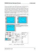
Figure 1-4:
Motor Lead Phasing with Oscilloscope.....................................1-5
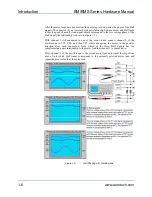
Figure 1-5:
Hall Phasing with Oscilloscope.................................................1-6
Figure 1-6:
Resolver and Motor Phasing.....................................................1-8
Figure 1-7:
Phasing of Sine, Cosine, and Marker Channels for
Rotary Encoder .......................................................................1-18
Figure 1-8:
BM75, BM130, BM200 Model Dimensions (NEMA 23) ..........1-23
Figure 1-9:
BM250, BM500 Model Dimensions (NEMA 34) .....................1-24
Figure 1-10:
BM800, BM1400 Model Dimensions (NEMA 42) ...................1-25
Figure 1-11:
BM2000, BM3400, BM4500 Model Dimensions (IEC
142) .........................................................................................1-26
Figure 1-12:
BMS60 and BMS100 Model Dimensions................................1-27
Figure 1-13:
BMS280 and BMS465 Model Dimensions..............................1-28
∇
∇
∇
Summary of Contents for BM Series
Page 6: ...Table of Contents BM BMS Series Hardware Manual iv www aerotech com...
Page 8: ...List of Figures BM BMS Series Hardware Manual vi www aerotech com...
Page 10: ...List of Tables BM BMS Series Hardware Manual viii www aerotech com...
Page 12: ...Declaration of Conformity BM BMS Series Hardware Manual x www aerotech com...
Page 50: ...Appendix A BM BMS Series Hardware Manual A 8 www aerotech com...
Page 56: ...Index BM BMS Series Hardware Manual Index 2 www aerotech com...
Page 58: ......


