


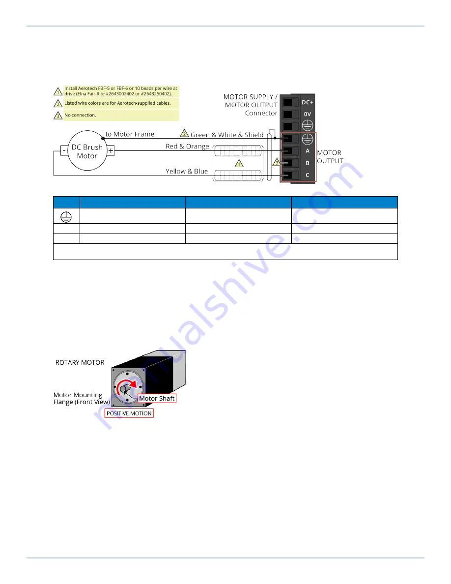
2.2.2. DC Brush Motor Connections
The configuration shown in
is an example of a typical DC brush motor connection. Refer
to
for information on motor phasing.
Figure 2-8:
DC Brush Motor Configuration
Table 2-9:
Wire Colors for Aerotech-Supplied DC Brush Motor Cables
Pin
Wire Color Set 1
(1)
Wire Color Set 2
Wire Color Set 3
Green & White & Shield
(2)
Green/Yellow & Shield
Green/Yellow & Shield
A
Red & Orange
Red
Red & Orange
C
Yellow & Blue
Black
Yellow & Blue
(1) Wire Color Set #1 is the typical wire set used by Aerotech.
(2) “&” (Red & Orange) indicates two wires; “ / ” (Green/White) indicates a single wire.
2.2.2.1. DC Brush Motor Phasing
A properly phased motor means that the positive motor lead should be connected to the ØA motor
terminal and the negative motor lead should be connected to the ØC motor terminal. To determine
if the motor is properly phased, connect a voltmeter to the motor leads of an un-powered motor:
1. Connect the positive lead of the voltmeter to the one of the motor terminals.
2. Connect the negative lead of the voltmeter to the other motor terminal.
3. Move or rotate the motor in the positive or clockwise (CW) direction by hand.
Figure 2-9:
Positive Motor Direction
4. If the voltmeter indicates a negative value, swap the motor leads and move the motor by hand in
the positive direction, again. When the voltmeter indicates a positive value, the motor leads have
been identified.
5. Connect the motor lead from the positive lead of the voltmeter to the ØA motor terminal on the
drive. Connect the motor lead from the negative lead of the voltmeter to the ØC motor terminal
on the drive.
For Aerotech-supplied systems, the motor, encoder and Hall sensors are correctly configured and
connection adjustments are not necessary.
iXC2/XC2
Hardware Manual
34
www.aerotech.com
Summary of Contents for Automation1 iXC2
Page 1: ...Revision 2 05 Automation1 iXC2 and XC2 PWM Digital Drives HARDWARE MANUAL...
Page 16: ...This page intentionally left blank iXC2 XC2 Hardware Manual 16 www aerotech com...
Page 18: ...Figure 1 2 XC2 High Performance PWM Amplifier iXC2 XC2 Hardware Manual 18 www aerotech com...
Page 26: ...This page intentionally left blank iXC2 XC2 Hardware Manual 26 www aerotech com...
Page 62: ...This page intentionally left blank iXC2 XC2 Hardware Manual 62 www aerotech com...
Page 72: ...Figure 3 8 Digital Outputs Schematic EB1 iXC2 XC2 Hardware Manual 72 www aerotech com...
Page 75: ...Figure 3 11 Digital Inputs Schematic EB1 Hardware Manual iXC2 XC2 www aerotech com 75...
Page 78: ...This page intentionally left blank iXC2 XC2 Hardware Manual 78 www aerotech com...
Page 84: ...This page intentionally left blank iXC2 XC2 Hardware Manual 84 www aerotech com...
Page 90: ...This page intentionally left blank iXC2 XC2 Hardware Manual 90 www aerotech com...
Page 96: ...Index iXC2 XC2 Hardware Manual This page intentionally left blank 96 www aerotech com...


