background image

Model 8310-XX-X-XN 


IM-493 

Aeroflex / Weinschel 

4


MODEL 8310-38-3-TN ATTENUATOR UNIT ASSEMBLY


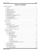
REPLACEABLE PARTS LIST (P/N 193-7038-11) ................... 47 

MODEL 8310-38-4-TN, ATTENUATOR UNIT ASSEMBLY


REPLACEABLE PARTS LIST (P/N 193-7038-12) .................. 47 

MODEL 8310-38-F / R-EN, ATTENUATOR UNIT ASSEMBLY


REPLACEABLE PARTS LIST (P/N 193-7038-13) ............ 48 

MODEL 8310-38-2-F / R -EN, ATTENUATOR UNIT ASSEMBLY


REPLACEABLE PARTS LIST (P/N 193-7038-14) ........ 48 

MODEL 8310-38-3-EN, ATTENUATOR UNIT ASSEMBLY


REPLACEABLE PARTS LIST (P/N 193-7038-15) .................. 49 

MODEL 8310-38-4-EN, ATTENUATOR UNIT ASSEMBLY


REPLACEABLE PARTS LIST (P/N 193-7038-16) .................. 49 

MODEL 8310-138-FN / -RN, ATTENUATOR UNIT ASSEMBLY


REPLACEABLE PARTS LIST (P/N 193-7138-5) ............ 50 

MODEL 8310-138-2-FN / -RN, ATTENUATOR UNIT ASSEMBLY


REPLACEABLE PARTS LIST (P/N 193-7138-6) ......... 51 

MODEL 8310-138-3-TN, ATTENUATOR UNIT ASSEMBLY


REPLACEABLE PARTS LIST (P/N 193-7138-7) .................. 52 

MODEL 8310-138-4-TN, ATTENUATOR UNIT ASSEMBLY


REPLACEABLE PARTS LIST (P/N 193-7138-8) .................. 53 

MODEL 8310-352-FN / -RN, ATTENUATOR UNIT ASSEMBLY


REPLACEABLE PARTS LIST (P/N 193-7403-5) ............ 54 

MODEL 8310-352-2-FN / -RN, ATTENUATOR UNIT ASSEMBLY REPLACEABLE PARTS LIST (P/N 193-7403-6) ......... 55 

MODEL 8310-352-3-TN, ATTENUATOR UNIT ASSEMBLY


REPLACEABLE PARTS LIST (P/N 193-7403-7) .................. 56 

MODEL 8310-352-4-TN, ATTENUATOR UNIT ASSEMBLY


REPLACEABLE PARTS LIST (P/N 193-7403-8 ................... 57 

ASSY, BASE UNIT W/ETHERNET (+15V) PARTS LIST (P/N 193-8034-3) ........................................................................ 58 

ASSY, BASE UNIT W/ETHERNET (+5V) PARTS LIST (P/N 193-8034-4) .......................................................................... 59 

8.   CONTACTING AEROFLEX / WEINSCHEL. ........................................................................................................... 60 

9.    AEROFLEX / WEINSCHEL WARRANTY  ............................................................................................................. 60 

10.  ASSEMBLY/WIRING DIAGRAMS 


MODEL 8310-1-X-XN  ASSEMBLY DRAWING ............................................................................... 193-7002-4A THRU -6A 

MODEL 8310-2-X-XN  ASSEMBLY DRAWING ......................................................................................... 193-7002-3A, -4A 

MODEL 8310-35-X-XN  ASSEMBLY DRAWING ........................................................................... 193-7035-9A THRU -16A 

MODEL 8310-36-X-XN  ASSEMBLY DRAWING ........................................................................... 193-7036-8A THRU -13A 

MODEL 8310-38-X-XN  ASSEMBLY DRAWING ........................................................................... 193-7038-9A THRU -16A 

MODEL 8310-138-X-XN  ASSEMBLY DRAWING ........................................................................... 193-7138-5A THRU -8A 

MODEL 8310-352-X-XN  ASSEMBLY DRAWING ........................................................................... 193-7403-5A THRU -8A 

BASE UNIT W/ETHERNET (+15 V) ASSEMBLY DRAWING ............................................................................. 193-8034-3A 

MODEL 8310  W/ETHERNET (+15 V) WIRING DIAGRAM   ................................................................................ 193-8135A 

BASE UNIT W/ETHERNET (+5 V) ASSEMBLY DRAWING ............................................................................... 193-8034-4A 

MODEL 8310 W/ETHERNET (+5 V)  WIRING DIAGRAM .................................................................................... 193-8136A 

MODEL 8310 W/ETHERNET, 8310-X-X-XN SPECIFICATION, ICD DRAWING .................................................. 089-4051A 

MODEL 8310 (75 OHM) W/ETHERNET, 8310-1-X-XN SPECIFICATION, ICD DRAWING .................................. 089-4052A 

MODEL 8310-138-X-XN SPECIFICATION, ICD DRAWING ................................................................................. 089-4066A 

MODEL 8310-352-X-XN SPECIFICATION, ICD DRAWING ................................................................................. 089-4065A 


Summary of Contents for SmartStep 8310

Page 1: ...ration Installation Manual Model 8310 SmartStep Programmable Attenuator Units w Ethernet This documentation may not be reproduced in any form for any purpose unless authorized in writing by Aeroflex W...

Page 2: ...d power outlet If using a 3 2 wire adapterbe sure to connect the ground leadtoearth ground Use the buddy system any time work involving active high voltage components is required Turn OFF the power be...

Page 3: ...ning and or drying can create airborne particles that may enter the eye Goggles faceshields should be worn DO NOT direct air stream towards self or other personnel Pressure should be restricted to a m...

Page 4: ...2 INTIAL SETUP 11 3 3 INPUT OUTPUT OPTIONS 11 12 3 3 1 POWER ENTRY MODULE ASSEMBLY 12 3 3 2 CHANNEL PORT CONNECTORS 12 3 3 3 MODE SELECT SWITCH 12 4 FRONT PANEL CONTROLS INDICATORS 13 5 REMOTE OPERAT...

Page 5: ...7 MODEL 8310 35 FN RN ATTENUATOR UNIT ASSEMBLY REPLACEABLE PARTS LIST P N 193 7035 9 38 MODEL 8310 35 2 FN RN ATTENUATOR UNIT ASSEMBLY REPLACEABLE PARTS LIST P N 193 7035 10 38 MODEL 8310 35 3 TN ATTE...

Page 6: ...LIST P N 193 7403 6 55 MODEL 8310 352 3 TN ATTENUATOR UNIT ASSEMBLY REPLACEABLE PARTS LIST P N 193 7403 7 56 MODEL 8310 352 4 TN ATTENUATOR UNIT ASSEMBLY REPLACEABLE PARTS LIST P N 193 7403 8 57 ASSY...

Page 7: ...to a single or multiple Aeroflex Weinschel programmable attenuators thus creating CH1 Channel 1 Note that when a Port is in use the Port indicator will be illuminated Dual channel units typically use...

Page 8: ...Under U S shipping regulations damage claims must be collected by the consignee DO NOT return the equipment to Aeroflex Weinschel until a claim for damages has been established 1 6 RESHIPMENT Use the...

Page 9: ...r Test ESDS Electrostatic Discharge Sensitive DIB Device Interface Bus TBD To Be Determined 1 11 SAFETY CONSIDERATIONS The Model 8310 XXX XN Attenuator Unit and all related documentation must be revie...

Page 10: ...TXD RXD RTS CTS DTR GND Baud Rates 2400 9600 19200 and 38400 Data Bits 8 Handshaking None RTS CTS XON XOFF Parity None Odd Even Indicators Tx Transmit and Rx Receive Ethernet TC IP 10 100 Base T Conne...

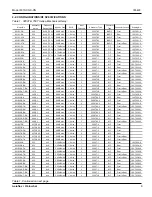
Page 11: ...1 3209T 64 5 N F Front 193 7036 8 8310 36 RN 64 5 0 1 dc 2 8 0 dB max 1 4 max 1 3209T 64 5 N F Rear 193 7036 8 8310 36 2 FN 64 5 0 1 dc 2 8 0 dB max 1 4 max 2 3209T 64 5 N F Front 193 7036 9 8310 36 2...

Page 12: ...52 2 RN 0 103 1 dB dc 6 0 GHz 6 0 dB max 1 55 2 3408T 103 N F Rear 193 7403 6 8310 352 3 TN 0 103 1 dB dc 6 0 GHz 6 0 dB max 1 55 3 3408T 103 N F Front Rear 193 7403 7 8310 352 4 TN 0 103 1 dB dc 6 0...

Page 13: ...N Series into a cabinet or rack if desired d Using the supplied power cord connect the 8310 XXX XN to the external power source e Setup the IEEE 488 bus address or other Communications options for you...

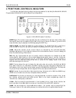
Page 14: ...rear panel allowing for single or multichannel configurations Standard Model 8311 XX X XN s are supplied with two PLANAR CROWN Type N connectors that can be mounted on the front or rear panel These co...

Page 15: ...ence value from which the attenuation may be set In this mode attenuation values may be positive or negative from the reference setting When REL is turned off the display returns to the actual attenua...

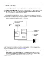
Page 16: ...am of the communications subsystem is shown below A copy of the Xport Users Guide and the Lantronix DeviceInstaller program is included on the provided CD For detailed information regarding the setup...

Page 17: ...or a detailed description of the available setup mode methods and options NOTE If you wish to change the serial port operation keep in mind that the settings must match in both places in order for the...

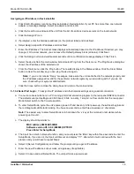
Page 18: ...ticular network segment you are working with If you are not sure check with your systems administrator j Click the Close button to close the dialog box and return to the main window 5 1 3 2 Serial Por...

Page 19: ...which automatically enables DHCP If a DHCP server exists on the network it provides the unit with an IP address gateway address and subnet mask when the unit boots up The DeviceInstaller software can...

Page 20: ...fies RS 232C 8 bit No Parity 1 stop bit Flow Flow control sets the local handshaking method for stopping serial input output The default setting for this parameter is 00 no flow control Port Number Th...

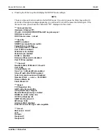
Page 21: ...MP Community Name public Telnet Setup is enabled TFTP Download is enabled Port 77FEh is enabled Web Server is enabled Web Setup is enabled ECHO is disabled Enhanced Password is disabled Port 77F0h is...

Page 22: ...rigger input disabled Channel 1 Match 00 00 Trigger input1 X Trigger input2 X Trigger input3 X Message Priority L Min notification interval 1 s Re notification interval 0 s Change Setup 0 Server 1 Cha...

Page 23: ...00 NS 010 100 103 173 0 NOTE The parameters shown above were obtained with the Xport set for DHCP mode IP 0 0 0 0 Enter QU to quit and exit diagnostics monitor mode 0 QU Place the MODE SELECT switch t...

Page 24: ...be set to 2400 9600 19200 or 34800 Parity selections include settings for None Even or Odd parity Handshaking may be enabled if desired and the method may be set to either hardware RTS CTS or software...

Page 25: ...es and directions are relative to the 6631 Pin Signal Name Description Direction 1 DCD unused 2 RxD Receive data input 3 TxD Transmit data output 4 DTR Signals DTE is on line output 5 GND Ground 6 DSR...

Page 26: ...ta available in the Error Event queue The Standard Event Status Register is used to report various IEEE 488 2 defined events The register contents may be accessed with the ESR Command An Event Status...

Page 27: ...ts and ended by a program message terminator If multiple commands are made on the same program line separate the individual command messages with a semicolon Arguments The 6853supports a variety of ar...

Page 28: ...llowable i e string8 has a max of 8 chars 5 4 3 OUTPUT DATA FORMAT Output data from the Model 6853 consists of a series of ASCII digits and message strings terminated with an ASCII Line Feed character...

Page 29: ...rn Value reg integer register Example s ESR returns the following 128 SRE Function Sets the Status Byte Enable Register Syntax SRE mask Argument s mask integer bitmask Remarks This function is used to...

Page 30: ...uery Syntax OPC Argument s none Remarks This function loads a 1 into the output queue when the Program Message Unit is executed Its primary use is to provide an indication of command completion by inc...

Page 31: ...e attenuation of the currently selected channel Return Value atten real attenuation value in dB Example s ATTN returns 63 00 REL Function Sets relative display mode for the current channel Syntax REL...

Page 32: ...sired stepsize value in dB Remarks This function sets the attenuation stepsize for the INCR and DECR commands for the current channel to atten The default value of the attenuator s stepsize is the int...

Page 33: ...thousand connection cycles Refer to Appendix A for more information about cables and connectors 6 3 SPECIAL CLEANING INSTRUCTIONS The cleaning procedures for 8310 are divided into five general groups...

Page 34: ...repeat step b as a rinse d When parts are thoroughly clean dry parts using 5 psi of clean moisture free compressed air or preferably dry nitrogen e Clean smaller mechanical parts or hardware by dippin...

Page 35: ...NECTED before attempting to change fuses CAUTION DO NOT connect or apply power to this instrument until the Power Entry Module Assembly has been adjusted to the operational line voltage a Disconnect t...

Page 36: ...ions arranged in alphanumerical sequence The letters A thru Z have precedence followed by numerals 0 thru 9 In addition to the reference designators that are listed some mechanical parts are also list...

Page 37: ...IM493 O S MANUAL MODEL 8310 1 NA W ETHERNET Refer to Aeroflex Weinschel Drawing 193 7001 4 Rev A for parts location Model 8310 1 2 FN RN Attenuator Unit Assembly Replaceable Parts List P N 193 7002 5...

Page 38: ...SSY BNC MALE TO 6 W10 W15 93459 B068 56 11 0 FEMALE BULKHEAD 75 OHM 8 090 301 LABEL STD 1 5 X 75 IN 1 NA 9 074 761 HOLE PLUG 1 2 HOLE NYLON BLACK 2 NA 83330 3092 10 193 9213 SPACER LOCKING 6 NA 12 NAS...

Page 39: ...V 20 IM493 O S MANUAL MODEL 8310 1 NA W ETHERNET Refer to Aeroflex Weinschel Drawing 193 7002 3 Rev A for parts location Model 8310 2 2 FN RN Attenuator Unit Assembly Replaceable Parts List P N 193 70...

Page 40: ...O S MANUAL MODEL 8310 W ETHERNET 1 NA Refer to Aeroflex Weinschel Drawing 193 7035 9 Rev A for parts location Model 8310 35 2 FN RN Attenuator Unit Assembly Replaceable Parts List P N 193 7035 10 Rev...

Page 41: ...4051 ICD ATTEN UNIT 8310 W ETHERNET 0 NA 20 IM493 O S MANUAL MODEL 8310 W ETHERNET 1 NA Refer to Aeroflex Weinschel Drawing 193 7035 11 Rev A for parts location Model 8310 35 4 TN Attenuator Unit Ass...

Page 42: ...O S MANUAL MODEL 8310 W ETHERNET 1 NA Refer to Aeroflex Weinschel Drawing 193 7035 13 Rev A for parts location Model 8310 35 2 F R EN Attenuator Unit Assembly Replaceable Parts List P N 193 7035 14 Re...

Page 43: ...D ATTEN UNIT 8310 W ETHERNET 0 NA 20 IM493 O S MANUAL MODEL 8310 W ETHERNET 1 NA Refer to Aeroflex Weinschel Drawing 193 7035 15 Rev A for parts location Model 8310 35 4 T EN Attenuator Unit Assembly...

Page 44: ...493 O S MANUAL MODEL 8310 1 NA W ETHERNET Refer to Aeroflex Weinschel Drawing 193 7036 8 Rev A for parts location Model 8310 36 2 FN RN Attenuator Unit Assembly Replaceable Parts List P N 193 7038 9 R...

Page 45: ...A 6 068 32 4 0 COAXIALCABLEASSY SMAM M 6 W8 W13 B068 32 4 0 CONFORMABLE DCTO18GHz 8 193 8044 ASSY CABLE CONTRTOATTENS 1 W7 CONTROLLERTOATTENS 11 090 301 LABELSTD 1 5X 75IN 1 NA 12 074 761 1 HOLEPLUG3...

Page 46: ...T 15V 0 NA 20 IM493 O S MANUAL MODEL 8310 1 NA W ETHERNET Refer to Aeroflex Weinschel Drawing 193 7036 11 Rev A for parts location Model 8310 36 2 F EN R EN Attenuator Unit Assembly Replaceable Parts...

Page 47: ...NFEMALE 6 NA 6 068 32 4 0 COAXIALCABLEASSY SMAM M 6 W8 W13 A068 32 4 0 CONFORMABLE DCTO18GHz 8 193 8044 ASSY CABLE CONTTOATTENS 1 W7 11 090 301 LABELSTD 1 5X 75IN 1 NA 12 074 761 1 HOLEPLUG3 8HOLE NYL...

Page 48: ...IM493 O S MANUAL MODEL 8310 1 NA W ETHERNET Refer to Aeroflex Weinschel Drawing 193 7038 9 Rev A for parts location Model 8310 38 2 FN RN Attenuator Unit Assembly Replaceable Parts List P N 193 7038 1...

Page 49: ...TEN UNIT W ETHERNET 15V 0 NA 20 IM493 O S MANUAL MODEL 8310 1 NA W ETHERNET Refer to Aeroflex Weinschel Drawing 193 7038 Rev A for parts location Model 8310 38 4 TN Attenuator Unit Assembly Replaceabl...

Page 50: ...IM493 O S MANUAL MODEL 8310 1 NA W ETHERNET Refer to Aeroflex Weinschel Drawing 193 7038 13 Rev A for parts location Model 8310 38 2 F R EN Attenuator Unit Assembly Replaceable Parts List P N 193 7038...

Page 51: ...9 4051 ICD ATTEN UNIT W ETHERNET 15V 0 NA 20 IM493 O S MANUAL MODEL 8310 1 NA W ETHERNET Refer to Aeroflex Weinschel Drawing 193 7038 15 Rev A for parts location Model 8310 38 4 T EN Attenuator Unit A...

Page 52: ...A M M 1 W9 068 32 4 0 CONFORMABLE DC TO 18 GHz 7 068 32 12 0 COAXIAL CABLE ASSY SMA M M 1 W10 93459 B068 32 12 0 CONFORMABLE DC 18 GHz 8 193 10806 ASSY DRIVER CABLE 1 W7 11 090 301 LABEL STD 1 5 X 75...

Page 53: ...M M 2 W9 W11 068 32 4 0 CONFORMABLE DC TO 18 GHz 7 068 32 12 0 COAXIAL CABLE ASSY SMA M M 2 W10 W12 93459 B068 32 12 0 CONFORMABLE DC 18 GHz 8 193 10806 ASSY DRIVER CABLE 1 W7 11 090 301 LABEL STD 1...

Page 54: ...MALE 6 NA 6 068 32 4 0 COAXIAL CABLE ASSY SMA M M 6 W9 W15 068 32 4 0 CONFORMABLE DC TO 18 GHz 8 193 10806 ASSY DRIVER CABLE 1 W7 11 090 301 LABEL STD 1 5 X 75 IN 1 NA 12 074 761 1 HOLE PLUG 3 8 HOLE...

Page 55: ...7005A 3 PLANAR CROWN TYPE N FEMALE 8 NA 6 068 32 4 0 COAXIAL CABLE ASSY SMA M M 8 W9 W17 068 32 4 0 CONFORMABLE DC TO 18 GHz 8 193 10806 ASSY DRIVER CABLE 1 W7 11 090 301 LABEL STD 1 5 X 75 IN 1 NA 13...

Page 56: ...B068 32 4 0 CONFORMABLE DC TO 18 GHz 7 068 32 12 0 COAXIAL CABLE ASSY SMA M M 1 W11 93459 B068 32 12 0 CONFORMABLE DC TO 18 GHz 8 193 8127 ASSY CABLE DRIVER 1 W7 11 090 301 LABEL STD 1 5 X 75 IN 1 NA...

Page 57: ...B068 32 4 0 CONFORMABLE DC TO 18 GHz 7 068 32 12 0 COAXIAL CABLE ASSY SMA M M 2 W11 W13 93459 B068 32 12 0 CONFORMABLE DC TO 18 GHz 8 193 8127 ASSY CABLE DRIVER 1 W7 11 090 301 LABEL STD 1 5 X 75 IN 1...

Page 58: ...6 NA 6 068 32 4 0 COAXIAL CABLE ASSY SMA M M 6 W10 W15 B068 32 4 0 CONFORMABLE DC TO 18 GHz 8 193 8127 ASSY CABLE DRIVER 1 W7 11 090 301 LABEL STD 1 NA 12 074 761 1 HOLE PLUG 3 8 HOLE NYLON BLACK 2 NA...

Page 59: ...3 PLANAR CROWN TYPE N FEMALE 8 NA 6 068 32 4 0 COAXIAL CABLE ASSY SMA M M 8 W10 W17 B068 32 4 0 CONFORMABLE DC TO 18 GHz 8 193 8127 ASSY CABLE DRIVER 1 W7 11 090 301 LABEL STD 1 NA 13 074 921 FEET NO...

Page 60: ...6A 28VDC 32 090 285 NAMEPLATE HIGH VOLTAGE 1 NA 33 193 9159 ASSY CABLE GND 1 W1 34 052 1 1 5 FUSE 1 5 AMP 250V 1 F1 75915 312 01 5 37 090 353 LABEL GROUND 1 NA 38 090 467 LABEL POWER INPUT 1 NA 39 MS5...

Page 61: ...TRANSITION 10 PIN 1 A6 TO 14 PIN INTERFACE 22 062 184 5 CONN SCREW LOCK 2 NA 71468 D20418 2 40 MS15795 803 WASHER FLAT 125 ID 250 OD 12 NA 41 MS35338 135 WASHER LOCK 4 10 NA 42 MS51957 14 SCR PAN HD...

Page 62: ...Aeroflex Weinschel warrants each product it manufactures to be free from defects in material and workmanship under normal use and service anywhere in the world Aeroflex Weinschel s only obligation un...

Page 63: ......

Page 64: ......

Page 65: ......

Page 66: ......

Page 67: ......

Page 68: ......

Page 69: ......

Page 70: ......

Page 71: ......

Page 72: ......

Page 73: ......

Page 74: ......

Page 75: ......

Page 76: ......

Page 77: ......

Page 78: ......

Page 79: ......

Page 80: ......

Page 81: ......

Page 82: ...ected in Paragraph A 6 A 3 MAKING INITIAL CONNECTIONS Exercise caution when mating cables Poor connections lead to poor system performance They can also damage not only the cable assembly but more sig...

Page 83: ...use tie wraps use the widest possible wrap and the lowest setting on the gun to ensure the minimum pressure on the cable A 5 2 STORING CABLES When storing cables minimize cable set by coiling them in...

Page 84: ...TN 8310 352 4 TN 8310 138 X XN Series All new Units C 8 09 Added Model 8310 1 XN 8310 38 XN 8310 2 XN Series All New Units D 12 09 Added Model 8310 36 XN Series All New Units E 1 09 Added Model 8310...

Page 85: ...rective 93 68 EEC relating to Electromagnetic Compatibility and Council Directive 73 23 EEC relating to LVD Safety by the application of EN50081 1 1992 Generic Emissions Standard Class B Equipment EN5...

Reviews: