


Model 8310-XX-X-XN
IM-493
Aeroflex / Weinschel
5
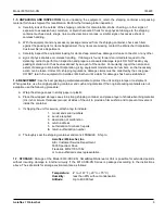
9. GENERAL INFORMATION:
1-1 PURPOSE:
This manual contains setup and operation information for the Aeroflex / Weinschel’s 8310-XXX-XN
Series of Programmable Attenuator Units with Ethernet Control. The manual also provides component location,
reference designators, part numbers, and nomenclature to identify all the assemblies and sub-assemblies of the
Attenuator Unit.
1-2 SCOPE:
This manual is to be used in conjunction with the operation and maintenance of an 8310-XXX-XN Series
of Programmable Attenuator Units with Ethernet Control. The manual also provides a description of each assembly;
assembly parts list; block diagrams: and general maintenance procedures to maintain the instrument.
1-3 EQUIPMENT DESCRIPTION:
Aeroflex / Weinschel’s 8310-XXX-XN Series of
Programmable Attenuator Units with Ethernet Control represents a new concept in
programmable attenuation for bench test and subsystem applications. Standard Model
8310-XXX-XN designs house and control various Aeroflex / Weinschel Programmable
Attenuator Models (3200T, 3400T, 150T, and 4200 Series) via front panel controls or
standard communications interfaces including Ethernet, GPIB (IEEE-488) and RS-
232/RS-422/RS485. Special configurations also exist where the RF section is designed
to specific customer requirements which can contain to multiple programmable
attenuations used in-conjunction with other coaxial devices such as switches, power
combiners, directional couplers, and filters creating single or multi-channel subsystems.
1-4 USING THE 8310-XXX-XN:
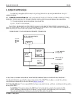
The 8310-XXX-XN Series provides front-panel and computer control for up to four
channels of attenuation, RF switching, or other functions. The 8310-XXX-XN combines the features of the Aeroflex /
Weinschel 8210A Device Controller with a front panel user interface to form a flexible, easy to use solution. Most
8310-XXX-XN Series are single channel configurations where RF signal is routed through either the front or rear
mounted Ports A & B connector (Ports A-A if the RF is routed front to rear) to a single or multiple Aeroflex / Weinschel
programmable attenuators thus creating CH1 (Channel 1). Note that when a Port is in use the Port indicator will be
illuminated. Dual channel units typically use Ports A and B for CH1 and Ports C and D for CH2 (Ports A-A if the RF is
routed front to rear for CH1 and Ports B-B for CH2). Multi-channel (3-4) units are generally routed front to rear and
configured as follows:
CH1 Port A (Front) to Port A (Rear)
CH2 Port B (Front) to Port B (Rear)
CH3 Port C (Front) to Port C (Rear)
CH4 Port D (Front) to Port D (Rear)
For specialized configurations refer to supplemental
information in the front of this manual for details.
Typically Aeroflex / Weinschel digital attenuators are bi-directional and the RF signal can be applied to either Port
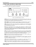
connector. Channels can be selected by toggling the front panel CHAN button until the desired CH1-CH4 indicator is
illuminated. Repeated depressions of the CHAN key will select the next available channel. The main display will show
the current attenuation setting of the channel. A new attenuation setting in dB may be entered using the INCR/DECR
or ENTRY keys. The front panel STEP key allows the user to define the attenuation step size used by the INCR and
DECR keys. Remember that the attenuation step size (resolution) is limited to the physical size of the internal
attenuator cells. For example a 0-70 unit with 10 dB steps can only be adjusted in 10 dB increments but larger
increments such as 20, 30, 40 dB can be set using this key.
The REL key allows the user to set relative mode for attenuators. When turned on, the currently displayed attenuation
value is used as a reference value from which the attenuation may be set. In this mode, attenuation values may be
positive or negative from the reference setting. When REL is
turned off, the display returns to the actual attenuation setting for
the channel. Refer to Section 5 for more detailed information
about the front panel keys and indicators. All 8310-XXX-XN
Series functions can also be controlled via standard
communications interfaces including Ethernet, GPIB (IEEE-488)
and RS-232/RS-422 /RS485. Refer to Section 6 for bus setup
and operating instructions when using the 8310-XXX-XN Series
in the remote mode.
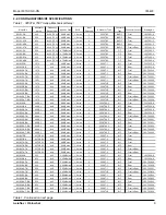
Model Number Index:
Summary of Contents for SmartStep 8310
Page 63: ......
Page 64: ......
Page 65: ......
Page 66: ......
Page 67: ......
Page 68: ......
Page 69: ......
Page 70: ......
Page 71: ......
Page 72: ......
Page 73: ......
Page 74: ......
Page 75: ......
Page 76: ......
Page 77: ......
Page 78: ......
Page 79: ......
Page 80: ......
Page 81: ......