Model 8310-XX-X-XN
IM-493
Aeroflex / Weinschel
15
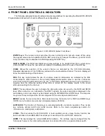
Ethernet Mode:
This position internally connects the serial port of the device server to the serial
port of the 8210A, allowing for network control of the unit. In this mode, the external serial port is
non-functional. The serial communication settings of the device server must be set to match that of
the 8210A for proper operation.
Console Mode:
This position connects the RS232 port directly to the XPort device server. This
mode allows the setup/configuration of the device server to be performed via the RS232 port. In this
mode, serial communications are fixed at 9600 N81. For detailed information regarding operation,
refer to the Xport Users Guide Chapters 5-8 (Setup Mode) and Chapter 11 (Monitor Mode).
5-1.2 Serial Port Setup:
By default, the unit is shipped configured for 9600 baud, no parity, and 1 stop bit, with no
handshaking required (9600N81). The rear-panel male DE-9 connector is configured as a DTE port (the same as a
typical PC) with the following pinout:
Pin
Name
Dir
Description
2
RXD
Receive Data (in)
3
TXD
Transmit Data (out)
5
GND
--
System
Ground
Connection to another DTE device (ie a PC) requires the use of a null-modem cable to swap pins 2 and 3.
Communication settings for the 8210A are controlled via the internal Serial/GPIB Settings DIP switch located on the
board (refer to the 8210A Manual IM-288), while the XPort serial configuration is set independently and can be done
using a variety of methods. Refer to the Xport Users Guide for a detailed description of the available setup mode
methods and options.
NOTE
If you wish to change the serial port operation, keep in mind that the settings must match in both
places in order for the XPort to communicate successfully with the 8210A when used in the
Ethernet control mode.
5-1.3 Ethernet Setup:
The network address of the XPort must be configured prior to use. There are several ways to
assign an IP address to the Xport. A general overview is provided here. For more detailed information and links to
video tutorials on performing many of these steps, refer to the information provided on the CD.
5-1.3.1 DeviceInstaller:
The Lantronix DeviceInstaller is a Windows-based program that can be used to setup the
Xport. Of the methods presented here, this is the simplest. However, the DeviceInstaller relies on the Xport being set
for DHCP. If a static IP has been previously assigned to the Xport, there is a high probability that the DeviceInstaller
will not be able to see the Xport, especially if the IP or Gateway network settings do not match that of the PC currently
being used. If that is the case, you will have to use one of the other methods outlined below.
To use the DeviceInstaller utility, first install it from the product CD or click on the link below to download the latest
version of DeviceInstaller.
http://ltxfaq.custhelp.com/app/answers/detail/a_id/644
a. Insert the product CD into your CD-ROM drive.
b. View Readme.txt located in the Lantronix Xport CD files Rev2 folder.
c. Select the desired DeviceInstaller and run the associated setup program within the folder.
d. Respond to the installation wizard prompts. (When prompted to select an installation type, select Typical.)
Summary of Contents for SmartStep 8310
Page 63: ......
Page 64: ......
Page 65: ......
Page 66: ......
Page 67: ......
Page 68: ......
Page 69: ......
Page 70: ......
Page 71: ......
Page 72: ......
Page 73: ......
Page 74: ......
Page 75: ......
Page 76: ......
Page 77: ......
Page 78: ......
Page 79: ......
Page 80: ......
Page 81: ......


