40
GR-UT699 Development Board
User Manual
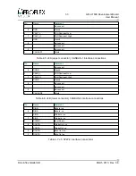
FUNCTION
ASIC pin
OPEN
SWITCH
CLOSED
PIO8
254
'1'
1
'0'
PIO9
255
'1'
2
'0'
PIO10
256
'1'
3
'0'
PIO11
257
'1'
4
'0'
PIO12
259
'1'
5
'0'
PIO13
260
'1'
6
'0'
PIO14
261
'1'
7
'0'
PIO15
262
'1'
8
'0'
Table 4-22: DIP Switch S4 'PIO[15..8]' definition
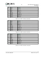
4.3 List of Jumpers
Name
Function
Type
Description
JP1
CONFIG
4x2 pin 0.1” Header
Header for DSU, PROM and WDOG enable
JP2
ETH_INTR
2 pin 0.1” Header
Enable Disable for Ethernet Interrupt
JP3
CAN_TERM0
2x2 pin 0.1” Header
Header for configuration of Termination of CAN0 i/f
JP4
CAN_TERM1
2x2 pin 0.1” Header
Header for configuration of Termination of CAN1 i/f
JP5
RAM_BANK
4x2 pin 0.1” Header
Header for configuration of RAM bank select
JP6
ROM_SELECT
4x2 pin 0.1” Header
Header for configuration of EEPROM/FLASH
JP7
PCI_CLK
2x2 pin 0.1” Header
Configures PCI Clocks for Host/Peripheral Mode
JP8
PCI_PULLUPS
10x2 pin 0.1” Header
Configures Host mode PCI signal pull ups
JP9
PCI_REQN
4 pin 0.1” Header
Configures PCI_REQN for Host/Peripheral Mode
JP10
PCI_GNTN
4 pin 0.1” Header
Configures PCI_GNTN for Host/Peripheral Mode
JP11
FP_LEDS
4x2 pin 0.1” Header
Header to connect or front panel LED's
JP12
VIN_SELECT
3pin 0.1” Header
Install jumper in position 1-2 for use with +5V main
power input is to be used to ge3.3V on board
and +2.5V (Vcore).
Connect 2-3 if 3.3V PCI power is to be used to provide
+3.3V on board and to ge2.5V (Vcore).
JP13
3.3V_SELECT
3 pin 0.1” Header
Install same as JP12
JP16
RESET_BREAK 2x2 pin 0.1” Header
Pins for Front Panel RESET and BREAK switches
JP17
SPW_CLK
2 pin 0.1” Header
Header to connect ASIC clock as SPW_CLK
JP18
PCI_RSTN
2 pin 0.1” Header
Connects board RESETN to PCI_RSTN for Host mode
Table 4-23: List and definition of PCB Jumpers
(for details refer to schematic)
© Aeroflex Gaisler AB
March 2013, Rev. 0.6

