39
GR-UT699 Development Board
User Manual
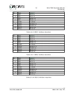
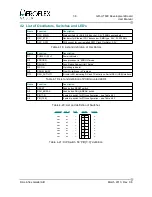
4.2 List of Oscillators, Switches and LED's
Name
Function
Description
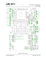
X1
OSC_MAIN
Main oscillator for ASIC DIL8 socket, 3.3V (75MHz as standard)
X2
OSC_ETH
Oscillator for Ethernet PHY transceiver, SMD type, 3.3V, 25.000MHz
X3
OSC_SPW
DIL8 socket for user installed SPW Clock Oscillator, 3.3V
Table 4-18: List and definition of Oscillators
Name
Function
Description
D1
POWER (3.3V)
Power indicator
D2
ERRORN
Leon processor in 'ERROR' mode
D3
DSUACT
Leon Debug Support Unit 'Active'
D4
WDOG
Watchdog indicator
D5
PROM_BUSY
Prom Write/Erase in Progress
D12
DSU_ACTIVITY
Bi-color LED indicating RX and TX activity on Serial DSU (USB) interface
Table 4-19: List and definition of PCB mounted LED's
Name
Function
Description
S1
RESET
Push button RESET switch
S2
DSU_BREAK
Push button DSU_BREAK switch
S3
PIO[7..0]
8 pole dip switch for PIO configuration – see Table 4-21
S4
PIO[15..8]
8 pole dip switch for PIO configuration – see Table 4-22
Table 4-20: List and definition of Switches
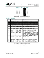
FUNCTION
ASIC pin
OPEN
SWITCH
CLOSED
PIO0
191
'1'
1
'0'
PIO1
192
'1'
2
'0'
PIO2
193
'1'
3
'0'
PIO3
194
'1'
4
'0'
PIO4
196
'1'
5
'0'
PIO5
197
'1'
6
'0'
PIO6
198
'1'
7
'0'
PIO7
199
'1'
8
'0'
Table 4-21: DIP Switch S3 'PIO[7..0]' definition
© Aeroflex Gaisler AB
March 2013, Rev. 0.6

