18
GR-UT699 Development Board
User Manual
2.8 Oscillators and Clock Inputs
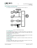
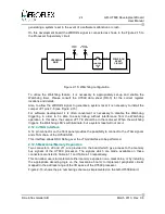
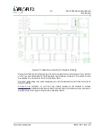
The oscillator and clock scheme for the UT699 ASIC is shown in Figure 2-9.
2.8.1 System Clock
The main oscillator for the
UT699
ASIC is a 75 MHz Crystal oscillator. This oscillator will be
a 4 pin DIL8 style oscillator, installed in a socket on the board. A zero-delay buffer circuit
(CY2305) is used to distribute the SYSCLK.
2.8.2 SPW_CLK
The
SPWCLK
can be derived from either the SYSCLK, a separate socketed on-board crystal
oscillator, or can be injected on a coaxial connector on the board.
2.8.3 Ethernet Clock
A dedicated 25MHz SMD oscillator is provided for the Ethernet Controller and PHY circuit
(see section 2.10).
2.8.4 PCI Clock
A dedicated 33.3MHz SMD oscillator and zero delay buffer are provided for the PCI clock.
For information on the configuration, please see section 2.11.
© Aeroflex Gaisler AB
March 2013, Rev. 0.6
Figure 2-9: Clock Distribution Scheme
SPW CLK
SMD
ZERO
DELAY
BUFFER
ZERO
DELAY
BUFFER
UT699RH
ASIC
PCI_CLK
TBD MHz
TBD MHz
ZERO
DELAY
BUFFER
ZERO
DELAY
BUFFER
DIL8 SOCKET
TBD MHz
TBD MHz
COAX CONNECTOR
DIL8 SOCKET
COAX CONNECTOR
MEMORY EXPANSION
CONNECTOR
MEMORY EXPANSION
CONNECTOR
SDCLK
SYS CLK
33.3 MHz
33.3 MHz
SDRAM
MODULE
SDRAM
MODULE
SMD
Ethernet
PHY
Ethernet
PHY
ETH_TXCLK
ETH_RXCLK
25 MHz
25 MHz
SDRAM
MODULE
PCI Backplane

