background image

21

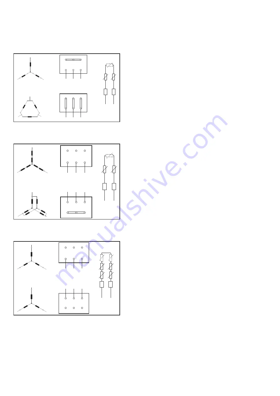
Electrical Connection

K

K

W2

U2

V2

U1

V1

W1

L2

L1

L3

W2

U2

V2

U1

V1

W1

L2

L1

L3

L1

U1

W2

L2

L3

V1

V2

U2

W1

L1

U1

W2

L2

L3

V1

V2

U2

W1

*2

*1

2U

2V

2W

1U

1V

1W

L2

L1

L3

2W

2U

2V

1U

1V

1W

L2

L1

L3

K

K

L1

1U

L2

L3

1V

2V

2U

2W

1W

L1

1U

2U

L2

L3

1V

2V

2W

1W

Speed 1:

750 rpm

Speed 2:

1500 rpm

*2

*1

K

K

2U

2V

2W

1U

1V

1W

L2

L1

L3

2W

2U

2V

1U

1V

1W

L2

L1

L3

L1

2U

L2

L3

2V

2W

L1

1U

L2

L3

1V

1W

Speed 1:

1000 rpm

Speed 2:

1500 rpm

*2

*1

Single-speed motor: 1500 rpm, voltage interchangeable

Motor version:
– up to 2.2 kW: 3 x 230 V with Δ connection,
3 x 400 V with Y connection
– above 3 kW: 3 x 400 V with Δ connection,
3 x 690 V with Y connection
2-3 PTC resistor sensors, depending on the size of the
motor
Total resistance R

K

 (20 °C) approx. 200-300 Ω

*1 PTC resistor
*2 Full motor protection device

Two-speed motor: 750/1500 rpm Dahlander connection Y/YY

Motor version:
8/4 pole
pole interchangeable
single winding with Dahlander connection Y/YY
2-3 PTC resistor sensors, depending on the size of the
motor
Total resistance R

K

 (20°C) approx. 200-300 Ω

*1 PTC resistor
*2 Full motor protection device

Two-speed motor: 1000/1500 rpm separate winding Y/Y

Motor version:
6/4 pole
pole interchangeable
two separate windings Y/Y
4-6 PTC resistor sensors, depending on the size of the
motor
Total resistance R

K

 (20°C) approx. 400-600 Ω

*1 PTC resistor
*2 Full motor protection device

Summary of Contents for EVO-M Series

Page 1: ...User s Manual EVO MODULAR AIR HANDLING UNITS ...

Page 2: ...2 Contents General Information 3 Transport Installation 5 Installation and Assembly 7 Installation of Components and Accessories 13 Electrical Connection 18 Commissioning and Maintenance 24 ...

Page 3: ...ucts have specific manufacturer s service instruction documents These are delivered with the Air Handling Unit In this case the indications in the OEM manual are valid and the service handbook in hand has only general or complementary character for the relating components 4 Liquid and gas storage Maximum working pressure for all coils is 15bar In case of coil connections to higher working pressure...

Page 4: ...rigerant with a temperature below than 2 C The unit controls should be designed in order to protect the exchanger against freezing AERA cannot be held responsible for damages coming from freezing de freezing operation The warranty does not cover overheating due to wrong use or improper control of electric heaters Dismantling or changing the units and or components without AERA approval or assistan...

Page 5: ...n 1000 kg the unit can be lifted from the transport lugsb delivered separately Figure 1 Crane operation procedure 1 Do not stand on the units If this is unavoidable ensure a more even weight distribution by the use of boards 2 Use battens to prevent damage of the top and sides of the units The forks must only be applied under the unit base frame and not against it Note The lift point should be as ...

Page 6: ...by lifting the unit slowly and evenly 6 All lifting points in one axis of the unit must be used when offloading and moving the unit 7 Slings are to be provided by the rigger and attached to all lifting points CAUTION Loading unloading and removal of single sections have to be carried out by employing means able to support the unit weight indicated in the technical sheet Ensure that the belts do no...

Page 7: ...n the discharge intake side of the unit DAMAGE TO THE UNIT During installation of EVO M units special care must be taken to ensure that no loads are applied to the floor panels During assembly work suitable measures should be taken to ensure that any loads are spread across the bottom profiles e g using grid walkways Installation Installation location The unit must be installed at a location that ...

Page 8: ...ould be applied If the unit has fresh air intake and discharge air make sure that the ducts are long enaugh so that the discharge air is not by passed to fresh air intake Choose an installation location where the fresh air intake will not be facing the main wind direction In areas where there is a heavy amount of snowfall the unit must be installed in a location where its operation will not be aff...

Page 9: ... structure borne sound isolation requirements exist We recommend the use of commercially available spring elements for ceiling mounting For very special acoustic requirements please consult an acoustics engineer to select the most suitable structure borne sound attenuation method Assembling the unit NOTE For detailed information please refer only to the documentation enclosed with the unit Data sh...

Page 10: ...e the supplied M8 x 70 screw Remove the lug screw and bushing at the dividing joint then secure the supplied M8 x 30 screw NOTE Because of danger of collision with transport lugs externally mounted dampers louvres flexible connections are partially supplied loose These components are field mounted and sealed by others NOTE Transportation lugs device must not be used to suspend the units on a perma...

Page 11: ...ng belts hoisting devices to heat exchanger connections condensate drains and door handles or use these to pull or push the equipment Position the unit parts as close to one another as possible prior to assembly Only use the unit base frame to pull the individual components together Units that do not have a base frame must be pulled together with tensioning belts These must be positioned round the...

Page 12: ...pipe and cable ducts to prevent air leakage and condensation using Polyurethane foam or similar insulation metarial not included in EVO M delivery scope Additional measure for double deck side by side units Connect both unit parts using the provided plates Additional measure for hygiene units Clean and seal all internal dividing joint grooves in the floor area The sealant is included in the scope ...

Page 13: ...able structure borne sound attenuation method Before you start with the coil connection check the following Drain valves must be installed at all low points in the water system to ensure that the water circuit can be fully drained in order to carry out maintenance or repairs A water drain with shut off valve must be installed in order to drain the unit s water system Air vents must be installed at...

Page 14: ... billion μg l Note These limiting values are only basic information about the water quality and do not form any basis for a guarantee Installation of air handling components for cooling heating DAMAGE TO THE UNIT When connecting the heat exchanger counter force must be applied using pliers to prevent damage The connections to the heat exchanger by others must always be tension free Mechanical and ...

Page 15: ...d from the formation of ice and freezing at ambient temperatures below the freezing point Use antifreeze in the water circuit if necessary NOTE Glycol may be used providing that it does not exceed 50 of the overall volume A higher quantity can cause operational faults Installation of evaporator condenser components ENVIRONMENTAL DAMAGE Dispose of any liquid spills refrigerant in an environmentally...

Page 16: ... temperature 20 C mS m μS cm 100 1000 30 300 12 120 Calcium Ca2 mol m g m 0 5 20 Carbonate hardness dH 4 Carbonate hardness with hardness stabilisation dH 20 Chloride Cl mol m g m 5 180 Sulphate SO4 2 mol m g m 3 290 KMnO4 consumption g m 50 20 10 Germ count organisms ml 1000 100 10 Legionella bacteria organisms ml 1 NOTE We recommend that you repeat the water analysis when installing a water soft...

Page 17: ...ormed using the equation below H mmWC Unit over underpressure Pa 10 The height difference between the water drain and hydraulic seal must also correspond to the dimension H mm WC Connect the siphon to the waste water system as shown in the illustration NOTE ON RISK OF FROST If there is a risk of frost the discharge pipe must be insulated and kept warm using a heating cable for example NOTE Underpr...

Page 18: ...ly conducting components or block them off Failure to do so may lead to serious injury or death NOTE The cable installation must be carried out in accordance with the enclosed wiring diagram of the unit and nationally applicable standards and guidelines Only one separate mains power cable should be used Never connect other units to this mains power cable Prerequisites Carry out a full visual inspe...

Page 19: ...re not permitted Connect the sensor only to full motor protection tripping devices INDUCTION EFFECTS We recommend the use of shielded cables such as JY st Y 2 x 2 x 0 5 to prevent the effects of induction on the PTC resistor measuring circuit Connect the shielding on one side with the potential equalisation PE Full motor protection electronics For motor protection we recommend our EVO M 912 MVS 1 ...

Page 20: ...ectric motors In order for the unit to operate properly it is important to connect it with a righthand rotating field Check the rotating field if necessary with a rotating field meter DAMAGE TO THE UNIT Correct assignment of the phase sequence to the specified rotational direction must be checked before the motor is connected If the wrong connection is made the motor fan may be damaged The termina...

Page 21: ...W 3 x 400 V with Δ connection 3 x 690 V with Y connection 2 3 PTC resistor sensors depending on the size of the motor Total resistance RK 20 C approx 200 300 Ω 1 PTC resistor 2 Full motor protection device Two speed motor 750 1500 rpm Dahlander connection Y YY Motor version 8 4 pole pole interchangeable single winding with Dahlander connection Y YY 2 3 PTC resistor sensors depending on the size of...

Page 22: ...interchangeable Speed 1 and 2 with Y YY Dahlander connection Speed 3 with Y connection separate winding 4 6 PTC resistor sensors depending on the size of the motor Total resistance RK 20 C approx 400 600 Ω 1 PTC resistor 2 Full motor protection device 1U 2U 3U 1W 2W 3W L2 L1 L3 1V 2V 3V 1U 2U 3U 1W 2W 3W L2 L1 L3 1V 2V 3V 1U 2U 3U 1W 2W 3W L2 L1 L3 1V 2V 3V L1 1U 3W 3U 1W 2 L 3 L 3V 1V L1 2U 2W L3...

Page 23: ... or current consumption varies in the individual phases the cause of this must be determined Frequency converter Settings are perrformed and adjusted during commisioning Service switch A lockable service switch must be installed near the fan section access door The wiring for service switches installed at the manufacturer s is led to the motor Installation and connection of the servo actuator If a...

Page 24: ...GER FROM ROTATING UNIT PARTS The fans do not come to a standstill immediately when the unit has been powered down You should therefore wait for at least 5 minutes until the fans have come to a standstill before starting maintenance and repair work DAMAGE TO THE UNIT When mounting EVO M units care must be taken to ensure that no loads are applied to the floor panels During installation and maintena...

Page 25: ...nections Check earthing Basic information regarding the cleaning of fins ELECTRICAL HAZARD AND DANGER FROM ROTATING UNIT PARTS OBSERVE PERSONAL PROTECTION MEASURES In doing so be sure to observe the safety information on page 24 DANGER FROM SHARP EDGES There is a danger that the thin fins will inflict cuts during cleaning The fin package must be cleaned to ensure that the heat exchanger continues ...

Page 26: ... roof Check side walls and cover strips reseal as necessary Check base frame and base frame skirt Clean external weather grille for fresh air and extract air Belt driven fan unit 3 months Check fan motor mountings also check for soiling damage and corrosion Check that anti vibration mounts are functioning correctly Check that belt guards are functioning correctly clean as necessary Check impeller ...

Page 27: ...with activated carbon cartridges are firmly seated In order not to reduce the service life of the costly activated carbon filter make sure that the pre and fine filtering stages are intact Grease filter every 3 6 months Wash out filter cells in cleaning bath Other filters Refer to the relevant documentation provided for information on maintenance Heater section LPHW 12 months Check for tightness a...

Page 28: ...fore the start of winter if necessary Evaporator condenser 12 months Clean and check evaporator condenser Make sure that all refrigeration components in direct evaporators refrigerating machine direct evaporator distribution manifold refrigerant lines etc are working efficiently Heat pipe 12 months Clean the heat transfer fins Clean condensate tray drain Check siphon top up as necessary Where a he...

Page 29: ...hes its end positions Sound attenuator 6 months Check the sound attenuating chamber and sound insulating splitters for contamination clean as necessary Units in general Commissioning of units for installation indoors The following commissioning steps must be carried out Carefully check the entire casing and parts such as Doors and service openings Handles and levers Connections with foam rubber se...

Page 30: ...aint impregnate etc as necessary Siphon Clean and refill existing siphons Hygiene inspection Check built in parts for contamination clean as necessary Carry out wipe disinfection disinfectant must not be aggressive towards the materials used only use alcohol based disinfectant Check the sealing materials for micro organisms and fungi Clean or replace the sealing materials as required Commissioning...

Page 31: ...UNIT PARTS OBSERVE PERSONAL PROTECTION MEASURES In doing so be sure to observe the safety information on page 24 DAMAGE TO UNIT Do not start up the fan against closed dampers The following commissioning steps must be carried out As a general rule the entire casing and all parts must be checked for damage and firm seating Remove transportation locks Check tension and alignment of belt Check the rot...

Page 32: ...e also the relevant manufacturer s instructions The following maintenance and inspection steps must be carried out Check that fans are securely mounted Check fans for soiling damage and corrosion Check that anti vibration mounts are functioning correctly Check that belt guards are functioning correctly clean as necessary Check impeller for imbalance Re tensioning renewing V belt Carry out the init...

Page 33: ...ng motor base or to renew it proceed as follows Slacken the lock nuts on the adjusting bolts Renew V belt if necessary Check adjust pulley alignment Fig 8 1 Tension V belt adjust using measuring device if possible calculate using frequency method Fig 8 1 Tighten lock nuts The deflection of the belt is approximately 5 20 mm when a load of P 20 30 N is applied depending on the distance between the a...

Page 34: ...recommended lubrication intervals for fan bearings without lifelong lubrication see Tab 8 4 Please refer to the manufacturer s operation manual for the relevant lubrication intervals Hexagon socket screws for securing pulley Shaft Sleeve V belt pulley Threaded hole for pressing out pulley Fig 8 3 Installing the V belt pulley Tab 8 4 Maximum tightening torques N can be relubricated Tab 8 5 Lubricat...

Page 35: ...following maintenance steps must be carried out Check electric motors for soiling damage and corrosion also check mountings Check electric motors for bearing noise have bearings replaced by specialist personnel if required Check impeller particularly welded seams for cracks have bearing replaced by specialist personnel if necessary Filter units Commissioning of filter unit ELECTRICAL HAZARD AND DA...

Page 36: ...nd therefore disposed of professionally and in an environmentally sustainable manner in accordance with applicable guidelines and legislation As a general rule all filters must be checked at regular intervals according to the operating conditions and renewed if necessary The following maintenance steps must be carried out Check filter for soiling damage and odours Clean filter section Check whethe...

Page 37: ... activated carbon filter ELECTRICAL HAZARD AND DANGER FROM ROTATING UNIT PARTS In doing so be sure to observe the safety information on page 24 The following maintenance steps must be carried out If the activated carbon is saturated when the planned number of operating hours has elapsed replace the filter In order to monitor the level of saturation in the filter the cartridge can be weighed to det...

Page 38: ...ECTION MEASURES In doing so be sure to observe the safety information on page 24 and page 25 The following commissioning steps must be carried out Check that the configuration of the water inlet and outlet connections is correct Counter flow principle with water inlet on the air outlet side Check that shut off devices and other fixtures have been installed correctly Open air vents if automatic air...

Page 39: ...ER FROM ROTATING UNIT PARTS AND SHARP EDGES OBSERVE PERSONAL PROTECTION MEASURES In doing so be sure to observe the safety information on page 24 and page 25 DANGER OF SCALDING Hot steam will escape if the air vents are opened There is a danger of scalding Open air vents carefully Always take suitable precautions before carrying out work The following commissioning steps must be carried out Open d...

Page 40: ...ing of electric heater section ELECTRICAL HAZARD AND DANGER FROM ROTATING UNIT PARTS In doing so be sure to observe the safety information on page 24 The heater coil may only be switched on if the minimum volume of air required for operation of the heater coil is flowing through it Make sure that the fan runs on for at least 3 minutes once the heater coil has been switched off Maintenance of elect...

Page 41: ...eliminator is not completely effective Verify that the installation position of the droplet eliminator is correct Check the velocity of air passing through the droplet eliminator standard DE wmax 3 8 m s TA 100 High performance wmax 5 8 m s Maintenance of cooler with without droplet eliminator ELECTRICAL HAZARD DANGER FROM ROTATING UNIT PARTS AND SHARP EDGES OBSERVE PERSONAL PROTECTION MEASURES In...

Page 42: ...er exposed to ambient temperatures higher than 60 C due to shutdown of the fan and or water temperatures heater coil 60 C The following commissioning steps must be carried out A protective gas charge must be available when making the connections Check that the configuration of the water inlet and outlet connections is correct Check that the shut off devices and other fixtures have been correctly i...

Page 43: ...ottom and the cold air flow fresh air must be at the top For commissioning see Commissioning of dampers and shut off dampers on page 47 Maintenance of heat pipe ELECTRICAL HAZARD DANGER FROM ROTATING UNIT PARTS AND SHARP EDGES OBSERVE PERSONAL PROTECTION MEASURES In doing so be sure to observe the safety information on page 24 and page 25 The following maintenance steps must be carried out Clean h...

Page 44: ...f the bypass damper as necessary Maintenance of plate heat exchanger ELECTRICAL HAZARD AND DANGER FROM ROTATING UNIT PARTS In doing so be sure to observe the safety information on page 24 The plate heat exchanger operates independently of any external mechanical or electrical actuators it has no moving parts and its service life is limited only by the effects of corrosion The following maintenance...

Page 45: ...nsate precipitates the danger of freezing increases The condensate migrates to the cold zone due to gravity and flow If a large quantity of conden sate precipitates the danger of freezing decreases If a small quantity of condensate precipitates the danger of freezing increases The condensate migrates to the warm zone due to gravity and flow The danger of freezing decreases The condensate migrates ...

Page 46: ...ampers on page 47 Maintenance of rotary heat exchanger The following maintenance steps must be carried out ELECTRICAL HAZARD DANGER FROM ROTATING UNIT PARTS AND SHARP EDGES OBSERVE PERSONAL PROTECTION MEASURES In doing so be sure to observe the safety information on page 24 and page 25 Vacuum clean heat exchanger fins regularly with a vacuum cleaner wet cleaning only permitted if a tray has been i...

Page 47: ...per actuator reaches its end position Maintenance of dampers and shut off dampers ELECTRICAL HAZARD AND DANGER FROM ROTATING UNIT PARTS OBSERVE PERSONAL PROTECTION MEASURES In doing so be sure to observe the safety information on page 24 The following maintenance steps must be carried out Vacuum clean dampers blow out never apply grease Detach the drive from the dampers and check dampers for ease ...

Page 48: ...s Office Varyap Meridian Grand Tower A Blok No 89 Ataşehir İSTANBUL TEL 90 216 504 76 86 FAX 90 216 504 76 90 Factory 3 Cadde No 13 Pancar OSB Torbalı İzmir TEL 90 232 799 0 111 FAX 90 232 799 01 14 R D Center 10032 sokak No 2 1 B 210 Bilimpark ITOB Menderes İZMİR aera com tr ...
Reviews: