background image

lnstallation & Maintenance Instructions

SERIES

8003G/H

8007G/H

8202G/H

l&M V 6584 R16 sec1 

OPEN-FRAME, GENERAL PURPOSE, WATERTIGHT/EXPLOSIONPROOF SOLENOIDS

ASCO® solenoid valves with design change letter 

“G” or “H’’ in the catalog number ( ex. 821 0G I) have 

an epoxy encapsulated ASCO® Red Hat II® solenoid. 

This solenoid replaces some of the solenoids with 

metal enclosures and open frame constructions. Follow 

these installation and maintenance instructions if your 

valve or operator uses this solenoid. 

See separate instructions for basic valve.

* DIN Plug Connector Kit No. K236034:

 Use this kit

only for solenoids with DIN terminals. The DIN plug

connector kit provides\a two pole with grounding con-

tact DIN Type 43650 construction (See Figure 6).

OPERATION 

Series 8003G/H and 8007G/H - When the solenoid is energized, 

the core is drawn into the solenoid base sub-assembly.  

IMPORTANT: When the solenoid is de-energized, the initial 

return force for the core, whether developed by spring,pres-

sure, or weight, must exert a minimum force to overcome re-

sidual magnetism created by the solenoid. Minimum return 

force for AC construction is 11 ounces, and 5 ounces for DC 

construction. 


Series 8202G/H - When the solenoid is energized, the disc 

holder assembly seats against the orifice. When the solenoid is 

de-energized , the disc holder assembly returns. 

IMPORTANT: 

Initial return force for the disc or disc holder assembly, 

whether developed by spring, pressure, or weight, must 

exert a minimum force to overcome residual magnetism 

created by the solenoid. Minimum return force is 1 pound, 5 

ounces. 

INSTALLATION 

Check nameplate for correct catalog number, service, and watt-

age. Check front of solenoid for voltage and frequency. 

A WARNING: Electrical hazard from the acces-

sibility of live parts. To prevent the possibility of 

death, serious injury or property damage, install 

the open • frame solenoid in an enclosure. 

FOR BLACK ENCLOSURE TYPES 7 AND 9 ONLY 

ACAUTlON: To prevent fire or explosion, do not install 

solenoid and/or valve where ignition temperature of hazard-

ous atmosphere is less than 165’C. On valves used for steam 

service or when a class “H” solenoid is used, do not install 

in hazardous atmosphere where ignition temperature is less 

than 180’C. See nameplate/ retainer for service. 

NOTE: 

These solenoids have an internal non-resetable thermal 

fuse to limit solenoid temperature in the event that extraordinary 

conditions occur which could cause excessive temperatures. 

These conditions include high input voltage, a jammed core, 

excessive ambient temperature or a shorted solenoid, etc. This 

unique feature is a standard feature only in solenoids with black 

explosionproof/dust-ignitionproof enclosures (Types 7 & 9).

A CAUTION: To protect the solenoid valve or operator, 

install a strainer or filter, suitable for the service involved 

in the inlet side as close to the valve or operator as possible. 

Clean periodically depending on service conditions. See 

ASCO Series 8600 and 8601 for strainers.

DESCRIPTION

Catalog numbers 8003G/H, 8007G/H and 8202G/H and are ep-

oxy encapsulated pull-type sole􀈵oids. The green solen01d with

lead wires and 1/2 conduit connection is designed to meet En-

closure Type !-General Purpose, Type 2-Dripproof, Types 3 and 

3S-Raintight, and Types 4 and 4X-Watertight. The black solenoid 

on catalog numbers prefixed “EF” or “EV” is designed to meet 

Enclosure Types 3 and 3S-Raintight, Types 4 and 4X-Watertight, 

Types 6 and 6P-Submersible, Type7, Explosionproof Class I, 

Division! Groups A, B, C, & D and Type 9, -Dust-lgnitionproof-

Class II, Division! Groups E, F & G. The Class II, Groups F & 

G Dust Locations designation is not applicable for solenoids or 

solenoid valves used for steam service or when a class “H” so-

lenoid is used. See Temperature Limitations section for solenoid 

identification and nameplate/ retainer for service. When installed 

just as a solenoid and not attached to an ASCO valve, the core 

has a 0.250-28 UNF-2B tapped hole, 0.38 or 0.63 minimum full 

thread. 

NOTE:

 Catalog number prefix “EV” denotes stainless steel 

construction. 

Solenoid catalog numbers 8202G/HI, 8202G/H3, 8202G/ H5 and 

8202G/H7 are epoxy encapsulated push-type, reverse-acting so-

lenoids having the same enclosure types as previously stated for 

Catalog numbers 8003G/Hl and 8003G/ H2. 8007G/H are 3-way 

solenoid operators with a pipe port or adapter, exhaust protector 

or vent at the top of the solenoid base sub-assembly.

Series 8003G/H, 8007G/H and 8202G/H solenoids are avail-

able in: 

Open-Frame Construction: 

The green solenoid may be 

supplied with 1/4” spade, screw or DIN terminals. (Refer to 

Figure 4)  

Panel Mounted Construction:

 These solenoids are specifi

-

cally designed to be panel mounted by the customer. Refer to 

Figures specified in this l&M and the section on Installation 

of Panel Mounted Solenoid for details.

Optional Features For Type 1 • General Purpose Construction 

Only

Junction Box: This junction box construction meets Enclosure Types 

2, 3, 3S, 4, and 4X. Only solenoids with 1/4” spade or screw terminals 

may have a junction box. The junction box provides a 1/2” conduit 

connection, grounding and spade or screw terminal connections within 

the junction box. (See Figure 5)

- SERVICE NOTICE-

l&M V 6584 R16 sec1 

©ASCO Valve, Inc. 50 Hanover Road, Florham Park, New Jersey 07932

www.ascovalve.com 

10

Summary of Contents for E-STOP09

Page 1: ...injury or property damage Please read the installation operation and maintenance instructions thoroughly before installing or servicing this appliance For your safety If you smell gas 1 Open windows 2...

Page 2: ...timer shutoff We have made every effort to thoroughly address all safety assembly and use issues for this product in the manual to follow We strongly encourage that you read and understand the materia...

Page 3: ...h the latest in safety technology Important safety information is presented throughout this manual for your safety and that of any users We have designed this product to provide you with many years of...

Page 4: ...S NEEDED SCHEMATICS BOX WIRING INSTRUCTIONS TIMER SETTINGS AND TIMER OPERATING INSTRUCTIONS E STOP BUTTON FUNCTION AND OPERATION ASCO VALVE INSTALLATION MAINTENANCE INSTRUCTIONS TESTING FOR GAS LEAKS...

Page 5: ...lease check the Timer box and Solenoid Valve with the following parts breakdown Even though we exercise extreme quality control procedures occasionally we will have a missing part or a part may have b...

Page 6: ...s timer shutoff requires a qualified gas appliance technician Installation is the responsibility of the customer All repair or services should be done by a qualified gas appliance technician Warning I...

Page 7: ...Valve Dimensions height 4 5 Width 4 Depth 2 25 Box Dimensions height 9 5 Width 5 75 Depth box 3 75 Including button 5 5 7...

Page 8: ...rtie doivent etre utilisees Rotate timer dial clockwise only Do not move the clock hands on the timer Moving the clock hands can damage the timer CLOCK MOTOR 120 VAC 60 HZ CLOCK MOTOR VOLTAGE AND CYCL...

Page 9: ...leaks or reason for activation before resetting Resetting Instructions Resetting the E STOP means a person manually intervenes and unlatches the button by rotating the button to the right Tamper Resi...

Page 10: ...temperature or a shorted solenoid etc This unique feature is a standard feature only in solenoids with black explosionproof dust ignitionproof enclosures Types 7 9 A CAUTION To protect the solenoid va...

Page 11: ...vided Additional Wiring Instructions For Optional Features Open Frame solenoid with 1 4 spade terminals For solenoids supplied with screw terminal connections use 12 18 AWG stranded copper wire rated...

Page 12: ...cleaning the valve Preventive Maintenance Keep the medium flowing through the solenoid opera tor or valve as free from dirt and foreign material as possible Periodic exercise of the valve should be co...

Page 13: ...dapter to 90 inch pounds maximum 10 2 Nm maximum Then make up piping or tubing to pipe adapter on solenoid 3 4 5 6 7 Disassembly and Reassembly of Solenoids Remove solenoid see Solenoid Replacement Re...

Page 14: ...id down Then pry here to lift nameplate retainer and push to remove red cap nameplate retainer grounding wire green or green with yellow stripes solenoid with 1 2I NPT 0 9375 26UNS 2A thread core AC c...

Page 15: ...nd grounding terminal socket head screw screw terminal block see note grounding screw and cup washer Junction Box Solenoid Note Junction box with screw terminals shown With screw terminal block remove...

Page 16: ...ASCO Valve Inc 50 Hanover Road Florham Park New Jersey 07932 l M V 6584_R16_sec2 www ascovalve com 16...

Page 17: ...Testing is also required after valve disassembly and reassembly for inspection cleaning or rebuilding OPERATION Normally Closed Valve is closed when solenoid is de energized open when energized NOTE N...

Page 18: ...ervice the valve should be operated at least once a month to insure proper opening and closing Depending on the medium and service conditions periodic inspection of internal valve parts for damage or...

Page 19: ...psi Between each test remove cup of water and operate valve 5 If seat leakage is detected turn off electrical power and depressurize valve Disassemble and check for proper placement of parts or any fo...

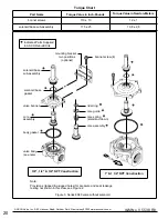
Page 20: ...o positions optional 3 8 1 2 3 4 NPT Construction 110 10 175 25 Torque Value in Newton Meters bonnet screw 4 rider ring core guide core spring small end down core assembly 12 1 19 8 2 8 1 1 1 4 NPT Co...

Page 21: ...nschlu erhalten Der Magnetantrieb kann je nach Bauart folgende Anschl sse haben Anschlu f r Ger testeckdose nach DIN 43650 Form A ISO 4400 oder 3 x DIN 46244 durch ordnungsgem e Montage der Ger testec...

Page 22: ...tingen hebben Stekeraansluiting volgens ISO 4400 of 3x DIN 46244 bij juiste montage wordt de dichtheidsklasse IP 65 verkregen Aansluiting binnen in het metalen huis d m v schroefaansluiting De kabeldo...

Page 23: ...up You have now finished the assembly of the gas shutoff timer We have tried to design your ESTOP09 with the finest materials and safety systems available Please do not modify any part of the product...

Page 24: ...th the maximum convenience and flexibility and more importantly to maximize the safety to your environment WARNING Never operate Gas Shutoff Timer in an explosive atmosphere and be sure to keep unit a...

Page 25: ...ndard Z223 1 If you have any questions whatsoever about the assembly or operation of this product please contact AEI Corporation or call us directly at 949 474 3070 or E mail info aeicorporation com F...

Page 26: ...hat you are happy with our products and support services Use of unauthorized parts or modification of our parts will void the warranty and can result in personal injury or property damage Warranty AEI...

Page 27: ...NINGS AND INSTRUCTIONS CAN RESULT IN SEVERE PERSONAL INJURY DEATH OR PROPERTY DAMAGE This warranty is for each Gas Timer Shutoff purchased and used in the 50 US states and the District of Columbia You...

Page 28: ...28...

Page 29: ...is ever a defective part or we need to quickly contact our customers regarding any added safety information regarding our products Your cooperation in this tracking system is extremely important Pleas...

Reviews: