24
24
2
1
2/3
1/3
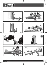
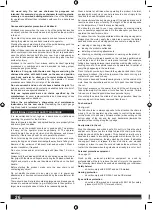
Figure 11
Figure 12
Figure 14
1
2
1/3
2/3
Figure 10
Figure 13
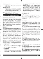
Figure 8
1
2
Figure 7
2
1
2/3
1/3
Figure 11
Figure 9
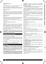
WARNING! Read all safety warnings and all instructions.
Failure to follow the warnings and instructions may result in electric
shock, fire and/or serious injury.
Save all warnings and instructions for future reference.
CHAINSAW SAFETY WARNINGS
Keep all parts of the body away from the saw chain when
operating the product. Before you start the chainsaw, make
sure the saw chain is not contacting anything.
A moment of
inattention while operating chainsaws may cause entanglement of
your clothing or body with the saw chain.
Always hold the chainsaw with your right hand on the rear
handle and your left hand on the front handle.
Holding the
chainsaw with a reversed hand configuration increases the risk of
personal injury and should never be done.
Hold the product by the insulated gripping surface only,
because the saw chain may contact hidden wiring.
Saw chains
contacting a “live” wire may make exposed metal parts of the power
tool “live” and could give the operator an electric shock.
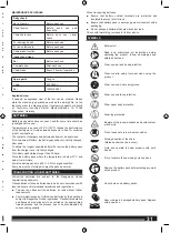
Wear safety glasses and hearing protection. Further protective
equipment for head, hands, legs and feet is recommended.
Adequate protective clothing will reduce personal injury by flying
debris or accidental contact with the saw chain.
TECHNICAL DATA
CORDLESS CHAINSAW
ACS18B30
ACS183060
Production code
4000 4604 70 01
4000 4604 70 01
000001-999999
000001-999999
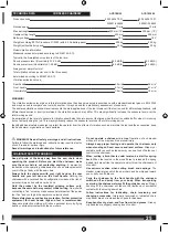
No-load speed
10 m/s
10 m/s
Max bar length
300 mm (12”)
300 mm (12”)
Usable cutting length
250 mm
250 mm
Battery voltage
18 V
18 V
Weight according EPTA-Procedure 01/2003 (with 6.0 Ah battery pack)
4.05 kg
4.05 kg
Weight (without battery pack)
3.3 kg
3.3 kg
Noise/vibration information
Measured values determined according to EN 60745-2-13.
Typically, the A-weighted noise levels of the tool are:
Sound pressure level (Uncertainty K= 2.5 dB)
85.3 dB(A)
85.3 dB(A)
Sound power level (Uncertainty K= 2.5 dB)
96.3 dB(A)
96.3 dB(A)
Always wear ear protectors!
Total vibration values (vector sum in the three axes)
determined according to EN 60745-2-13.
Vibration emission value a
h
Rear handle
9.5 m/s
2
9.5 m/s
2
Front handle
6.1 m/s
2
6.1 m/s
2
Uncertainty K
1.5 m/s
2
1.5 m/s
2
WARNING!
The vibration emission level given in this information sheet has been measured in accordance with a standardised test given in EN 60745
and may be used to compare one tool with another. It may be used for a preliminary assessment of exposure.
The declared vibration emission level represents the main applications of the tool. However if the tool is used for different applications, with
different accessories or poorly maintained, the vibration emission may differ. This may significantly increase the exposure level over the
total working period.
An estimation of the level of exposure to vibration should also take into account the times when the tool is switched off or when it is running
but not actually doing the job. This may significantly reduce the exposure level over the total working period.
Identify additional safety measures to protect the operator from the effects of vibration such as: maintain the tool and the accessories, keep
the hands warm, organisation of work patterns.
Summary of Contents for ACS183060
Page 1: ...ACS18B30 ACS183060 ...
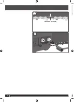
Page 2: ...2 2 ENGLISH 1 2 3 Picture section with operating description and functional description 4 ...
Page 4: ...4 4 20 19 12 10 ...
Page 5: ...5 5 START STOP 8 16 21 13 14 23 15 ...
Page 6: ...6 6 12 13 6 9 10 11 8 7 ...
Page 7: ...7 7 17 18 16 15 14 1 2 3 4 5 ...
Page 8: ...8 8 Remove the battery pack before starting any work on the machine 1 click 2 1 2 ...
Page 9: ...9 9 75 100 0 25 50 75 25 50 ...
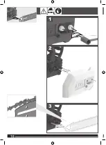
Page 10: ...10 10 2 1 3 ...
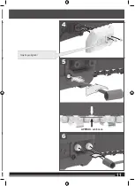
Page 11: ...11 11 5 4 6 Only finger tighten APPROX 4 5 5 mm ...
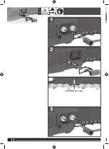
Page 12: ...12 12 FLATS APPROX 4 5 5 mm 2 3 1 ...
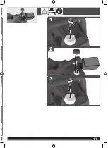
Page 13: ...13 13 2 3 1 ...
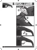
Page 14: ...14 14 1 2 3 START STOP ...
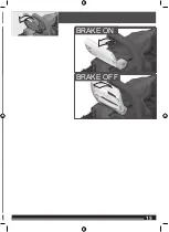
Page 15: ...15 15 BRAKE ON BRAKE OFF ...
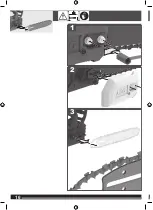
Page 16: ...16 16 2 3 1 ...
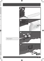
Page 17: ...17 17 5 6 7 4 Only finger tighten ...
Page 18: ...18 18 FLATS APPROX 4 5 5 mm 8 ...
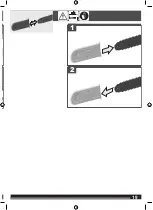
Page 19: ...19 19 2 1 ...
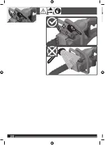
Page 20: ...20 20 ...
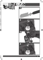
Page 21: ...21 21 2 3 1 4 ...
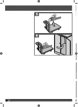
Page 22: ...22 22 6 5 ...
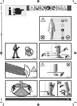
Page 23: ...23 23 Figure 1 Figure 6 Figure 2 Figure 3 Figure 5 1 3 2 5 cm 2 in 5 cm 2 in Figure 4 ...
Page 33: ...uct ant 30 ing 14 bH out 224 ...
Page 34: ......
Page 35: ......

