Screw Compressor Central Chiller
Chapter 3: Installation
20
Return (From Process)
Bring the chilled water returning from the process to the pump tank warm
(From Process)
side. This line is sized according to the flow rate from the process to the pump tank. See
Page 16 for more information on piping considerations.
Caution!
Do
not
use the Screw Compressor Central Chiller to support piping.
Makeup
Connect a city water source to maintain water level in the pump tank. See page 21 for water
treatment considerations.
Note:
If glycol is to be added to the system, DO NOT DO THIS!
Overflow
Connect the
OVERFLOW
outlet to an approved, trapped drain to permit excess water in the
pump tank to overflow to the drain. The overflow line is sized according to the size of the
pump tank.
Flow Switch
This central chiller station is equipped with a flow switch which shuts down the chiller if the
evaporator water flow falls below a safe operating gallons-per-minute (liters-per-minute)
flow rate.
Control Nozzle
All central chilling station evaporators have two control nozzles. The flow switch, freezestat,
and flush port are located in the control nozzle. Pressure gages are mounted in the control
nozzles to aid in achieving proper flow through the evaporator and balancing flows.
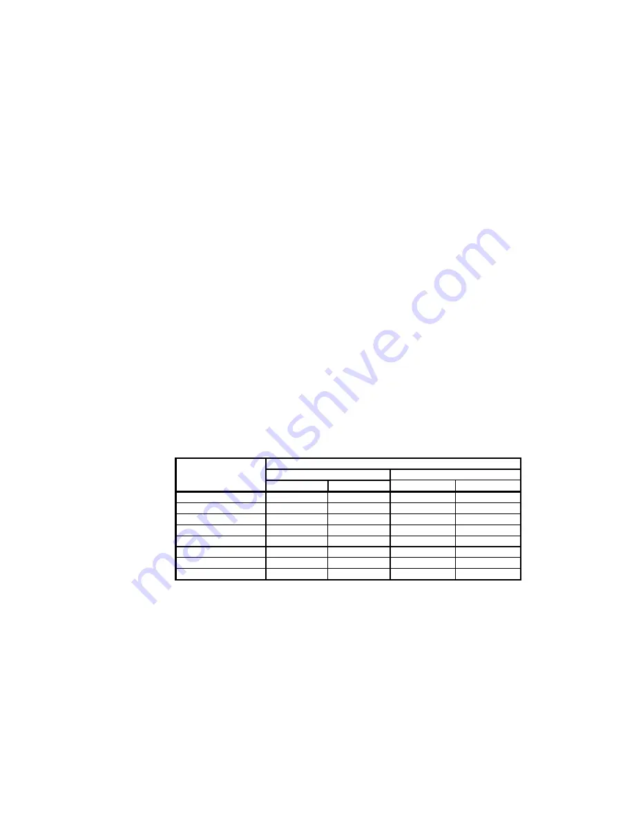
Pressure drop between evaporator entering water pressure and evaporator leaving water
pressure can be converted to gallons per minute using the pressure drop chart below.
Water Side Pressure Drop
Condenser (each)
Evaporator (each)
Model
Number
Flow (gpm)
PD (psi)
Flow (gpm)
PD (psi)
RSW/R60
91
4.0
72
5.3
RSW/R75
102
4.7
90
4.5
RSW/R90
117
4.4
107
5.6
RSW/R100
150
5.5
123
3.9
RSW/R115
166
4.3
140
3.0
RSW/R145
196
4.1
175
4.8
RSW/R165
219
4.1
200
4.6
RSW/R195
278
4.7
232
6.0
To Drain
Connect to a 1
½
” line (approx. 63 mm) leading to an approved, trapped drain. You can drain
the pump tank if necessary.
Note:
If glycol is added to the system, DO NOT DO THIS!

