background image

Screw Compressor Central Chillers 

Chapter 1:  Safety 

vi of 77 


Chapter 1:  Safety 

1-1  How to Use This Manual 

Use this manual as a guide and reference for installing, operating, and maintaining your 
screw compressor central chiller.  The purpose is to assist you in applying efficient, proven 
techniques that enhance equipment productivity. 

This manual covers only light corrective maintenance. No other maintenance should be 
undertaken without first contacting a service engineer. 

The Functional Description section outlines models covered, standard features, and safety 
features.  Additional sections within the manual provide instructions for installation, pre-
operational procedures, operation, preventive maintenance, and corrective maintenance. 

The Installation chapter includes required data for receiving, unpacking, inspecting, and setup 
of the screw compressor central chiller. We can also provide the assistance of a factory-
trained technician to help train your operator(s) for a nominal charge. This section includes 
instructions, checks, and adjustments that should be followed before commencing with 
operation of the Central Chiller.   These instructions are intended to supplement standard 
shop procedures performed at shift, daily, and weekly intervals. 

The Operation chapter includes a description of electrical and mechanical controls, in 
addition to information for operating the Central Chiller safely and efficiently. 

The Maintenance chapter is intended to serve as a source of detailed assembly and 
disassembly instructions for those areas of the equipment requiring service.  Preventive 
maintenance sections are included to ensure that your Central Chiller provides excellent, long 
service.  

The Troubleshooting chapter serves as a guide for identification of most common problems.  
Potential problems are listed, along with possible causes and related solutions. 

The Appendix contains technical specifications, drawings, schematics, parts lists, and 
available options.  A spare parts list with part numbers specific to your machine is provided 
with your shipping paperwork package.  Refer to this section for a listing of spare parts for 
purchase.  Have your serial number and model number ready when ordering. 

Safety Symbols Used in this Manual 

The following safety alert symbols are used to alert you to potential personal injury hazards. 
Obey all safety messages that follow these symbols to avoid possible injury or death. 

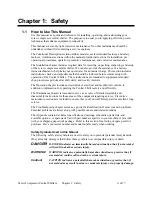
DANGER! 

DANGER indicates an imminently hazardous situation that, if not avoided, 
will result in death or serious injury. 

WARNING! 

WARNING indicates a potentially hazardous situation or practice that, if 
not avoided, could result in death or serious injury. 

Caution! 

CAUTION indicates a potentially hazardous situation or practice that, if 
not avoided, may result in minor or moderate injury or in property damage. 


Summary of Contents for A0551794 RS Series

Page 1: ...___________________ _________________________ _________________________ _________________________ _________________________ _________________________ We are committed to a continuing program of produc...

Page 2: ...t A certified copy of our invoice is available upon request The original Bill of Lading is attached to our original invoice If the shipment was prepaid write us for a receipted transportation bill Adv...

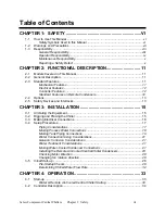
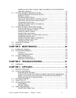
Page 3: ...3 2 5 Safety Devices and Interlocks 13 CHAPTER 3 INSTALLATION 15 3 1 Uncrating the Equipment 15 3 2 Rigging and Placing the Chiller 15 3 3 Making Electrical Connections 16 3 4 Setup Procedures 17 Pipi...

Page 4: ...s 54 Configuration Menu Screen 56 Viewing and Setting System Temperatures 58 Viewing Compressor Run Times 60 Viewing Pump Run Times 62 4 5 Operation Procedures 63 4 6 Shutdown 63 CHAPTER 5 MAINTENANCE...

Page 5: ...essor Central Chillers Chapter 1 Safety v 7 7 Central Chiller Identification Serial Number Tag 76 7 8 Technical Assistance 77 Parts Department 77 Service Department 77 Sales Department 77 Contract Dep...

Page 6: ...mechanical controls in addition to information for operating the Central Chiller safely and efficiently The Maintenance chapter is intended to serve as a source of detailed assembly and disassembly i...

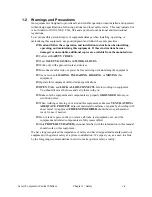
Page 7: ...rvicing or maintaining the equipment Use care when LOADING UNLOADING RIGGING or MOVING this equipment Operate this equipment within design specifications OPEN TAG and LOCK ALL DISCONNECTS before worki...

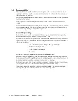
Page 8: ...onnel must realize that every day safety is a vital part of their jobs If your main concern is loss of productivity remember that production is always affected in a negative way following an accident...

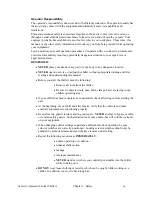
Page 9: ...ng and understanding this manual x Before you start the chiller check the following x Remove all tools from the chiller x Be sure no objects tools nuts bolts clamps bars are laying in the chillers ope...

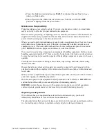
Page 10: ...use handling equipment portable A frames electric boom trucks fork trucks overhead cranes be sure the load does not exceed the capacity of the handling equipment or cause it to become unstable Carefu...

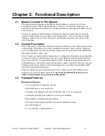
Page 11: ...manual lists information specific to these units Screw Compressor central chilling stations may be configured with stainless steel pump tanks for use as reservoirs for chilled water processes These d...

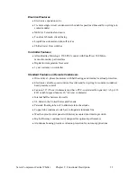
Page 12: ...es on Remote Condensers x Direct drive 3 phase fan motors with ball bearings and internal overload protection x Electronic variable speed control of lead fan and fan cycling for constant condenser hea...

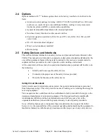
Page 13: ...mmended to supplement these procedures in order to provide a safer working environment At the completion of this section the operator and maintenance personnel will be able to do the following x Ident...

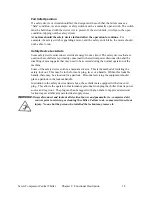
Page 14: ...ion and the disabling of moving parts that may need to be accessed during the normal operation of the machine Some of the safety devices utilize a manual activator This is the method of initiating the...

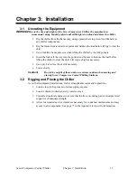
Page 15: ...ets and be sure to balance the load before lifting the chiller to clear the skid Lift only as high as necessary 5 Use a pry bar to free the skid if necessary 6 Lower slowly Caution Due to the weight o...

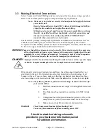
Page 16: ...ds and cause severe damage to the compressor Again check the unit nameplate for correct voltage and amperage Compressors must be wired in sequence ABC If not wired properly the unit can be damaged if...

Page 17: ...ections water cooled condenser connections and connecting the remote air cooled condenser We recommend that you carry out these procedures in the order given here Note Before carrying out these proced...

Page 18: ...nd circuit isolation optional pressure gauges can be installed To Process The chilled water supply outlet should be piped to the cold side of the pump tank From Process The chilled water return for wa...

Page 19: ...ve grade ethylene or propylene glycol with rust inhibitor to provide protection down to 20 F 12 C below the operating temperature you want Figure 1 below shows the proper mixtures needed to provide pr...

Page 20: ...s down the chiller if the evaporator water flow falls below a safe operating gallons per minute liters per minute flow rate Control Nozzle All central chilling station evaporators have two control noz...

Page 21: ...er may be used in the system without problem in other locations it will result in large deposits of scale and corrosion We offer a complete line of water treatment equipment Contact your sales represe...

Page 22: ...with an electro mechanical safety feature which opens the control circuit if the system condensing pressure exceeds a safe level The table below lists the manufacturer settings for this safety feature...

Page 23: ...Note Piping should be type L or type K refrigerant grade copper tubing only Proper sizing and installation has a significant effect on system performance reliability and safety Interconnecting Refrige...

Page 24: ...e feet x Refer to page XX of the Appendix for the location of traps x Refrigeration lines must not be crossed i e chiller liquid lines are to be piped to condenser liquid lines x HFC134A refrigerant a...

Page 25: ...charge determination Figure 3 Liquid Line Sizing 30 65 F Leaving Water Temperature Liquid Line Size O D Equiv Ft 35 hp 40 hp 50 hp 60 hp 70 hp 80 hp 90 hp 110 hp 25 7 8 7 8 1 1 8 1 1 8 1 1 8 1 3 8 1 3...

Page 26: ...2 1 8 2 1 8 2 5 8 2 5 8 2 5 8 3 1 8 3 1 8 3 5 8 100 2 1 8 2 1 8 2 5 8 2 5 8 3 1 8 3 1 8 3 1 8 4 1 8 125 2 1 8 2 5 8 2 5 8 3 1 8 3 1 8 3 1 8 3 5 8 4 1 8 150 2 1 8 2 5 8 2 5 8 3 1 8 3 1 8 3 5 8 3 5 8 4...

Page 27: ...charge Line R134a Lbs Liquid Line R134a Lbs 35 20 35 19 7 8 1 0 24 3 40 25 40 24 1 1 8 1 7 41 4 50 30 50 29 1 3 8 2 6 63 0 60 35 60 29 1 5 8 3 6 89 2 70 40 70 36 2 1 8 6 3 155 1 80 50 80 43 2 5 8 9 7...

Page 28: ...on the unit Water Pump A positive pressure of 20 to 30 psi 137 9 to 206 8 kPa 1 38 to 2 07 bars on the TO PROCESS line indicates correct pump rotation Condenser Fan On central chillers with remote ai...

Page 29: ...R OUT connections Provide an adequate condenser water supply 2 gpm per ton for city water or 3 gpm per ton for tower water operation 12 Remove all tools foreign matter and debris from the pump tank re...

Page 30: ...piping is being filled 22 Once the system is full open the pump discharge butterfly valve fully 23 Check your work and proceed to the Startup procedure Remote Air Cooled Central Chiller Startup Check...

Page 31: ...leads for reversing rotation x Do not use contactor or motor leads for phase matching x Compressor damage will occur if the compressor is run in reverse The compressor motor protector checks for corr...

Page 32: ...s being filled 23 Open the discharge fully when system is filled 24 Check your work and proceed to the Startup procedure in the following section Determining Chilled Water Flow Rate To determine flow...

Page 33: ...do this 4 Fifteen 15 seconds after the last pump turns on the first compressor will turn on Based on the temperature of the water the controller will turn on compressors every 15 seconds 5 Adjust the...

Page 34: ...e the unit Stop The Stop push button lets you de energize the unit Touchscreen Interface The touchscreen interface gives you control over the chilling station It has an easy to use control menu that l...

Page 35: ...Screw Compressor Central Chiller Chapter 4 Operation 35 Figure 2 Advanced Touchscreen Controller...

Page 36: ...tatus screen do not have sufficient space to display a prompt that the F4 performs this function However the F4 button will always move to the previous screen and will eventually return to the Main Me...

Page 37: ...chiller was configured to operate the chilled water pump tank x ACTIVE ALARM LIST shows all of the active alarms Those alarms which are currently preventing the chiller from functioning if fatal alarm...

Page 38: ...display one of the following states 1 OFFLINE This indicates that the compressor has been turned off in the compressor enable disable screen The compressor will not be called to operate until it has b...

Page 39: ...en Only pumps that are enabled in the system will be shown on this screen Pumps will display one of the following states 1 OFFLINE This indicates that the pump has been turned off in the pump enable d...

Page 40: ...ondition Screen To acknowledge the alarm press F1 to clear the alarm It will then appear in the alarm history screen Except for High and Low Water Temperature and Low Refrigerant Pressure these alarms...

Page 41: ...oints Operating the chiller compressors To enable or disable the individual compressors start at the Main Menu then 1 Press the or buttons on the right side of the screen to highlight CONFIGURATION ME...

Page 42: ...Times and Activating Compressor Lead Lag Operation While in the Configuration Menu the compressor rotation screen allows the customer to enable or disable the rotation of compressors While viewing the...

Page 43: ...hlight either CONFIGURATION MENU 2 Press 3 Highlight PUMP ENABLES 4 Press 5 Highlight the pump you want to operate The Pump Enables Screen appears Pump Enables Screen Any pump that is disabled to the...

Page 44: ...allows the customer to enable or disable the rotation of compressors While viewing the screen for the applicable rotation pressing F1 will toggle the rotation function On or Off Pressing the F2 button...

Page 45: ...ic values Setting System Temperatures The chiller setpoints are set through the configuration menu Starting from the Main Menu 1 Press the or buttons to highlight CONFIGURATION MENU 2 Press 3 Highligh...

Page 46: ...omponent that is not included in the system will not accumulate time The Compressor Run Time screen displays Compressor Run Time Display Screen Two hourmeters are kept for each compressor in the syste...

Page 47: ...s not included in the system will not accumulate time The Pump Run Time screen displays Compressor Run Time Display Screen Two hourmeters are kept for each compressor in the system The first is a life...

Page 48: ...based on options and system configuration at the time of order These screens are the basic ones to startup the chiller The Advanced touchscreen interface is the manager of your screw compressor centr...

Page 49: ...ystem x Active Alarms contains the current alarm s of the system x Al arm History contains the last thirty 30 alarms that were activated x If the chiller was configured to operate the chilled water pu...

Page 50: ...ime and resettable hour meters to show the number of hours that the process and recirculation pumps have been running x PanelView Utilities and ACS Service are both password protected sections of the...

Page 51: ...t point 2 Compressor anti recycle time is two 2 minutes To view the status of the chiller compressors start at the Main Menu screen then 1 Press the Up or Down buttons on the right side of the screen...

Page 52: ...dy to run However the current loading does not require the compressor to be running This compressor will be automatically started when needed The color code for this indication is yellow 3 RUNNING Com...

Page 53: ...ter Pump Tank Configuration Screen appears Figure 6 Chilled Water Pump Tank Configuration Screen Only pumps that are included in the system will be shown on this screen Pumps will display one of the f...

Page 54: ...e alarm conditions as well as the alarm history for the entire history The list of system alarms that are tracked are as follows x Chilled Water High Temperature Alarm x Chilled Water Low Temperature...

Page 55: ...compressor or circuit is deactivated The load will automatically shift to any other compressors that are currently ON LINE but not running Lead Lag rotation will continue to function Compressors that...

Page 56: ...ompressors To enable or disable the individual compressors start at the Main Menu then 1 Press the Up or Down buttons on the right side of the screen to highlight Chiller Configuration 2 Press the but...

Page 57: ...d Water Pump Tank Configuration 2 Press The Pump Enables Screen appears Figure 9 Chilled Water Pump Tank Configuration Screen Any pump that is disabled to the OFF LINE position will not be called to o...

Page 58: ...otation button The status of the button will change to Enabled green background or Disabled red background Setting Pump Rotation Times and Activating Pump Rotation Operation The system automatically r...

Page 59: ...t at the Main Menu and 1 Use the Up or Down arrows to highlight Chilled Water System Status 2 Press The system status displays Figure 10 Chilled Water System Status Screen Note If you have a metric ve...

Page 60: ...the Main Menu 1 Press the Up or Down buttons to highlight Chiller Configuration 2 Press 3 Touch the Process Set point button The input display screen appears Figure 11 Temperature Input Display Screen...

Page 61: ...em will not accumulate time The Compressor Run Time screen displays Figure 8 Compressor Run Time Display Screen Two hourmeters are kept for each compressor in the system The first is a lifetime meter...

Page 62: ...ot included in the system will not accumulate time The Pump Run Time screen displays Figure 9 Pump Run Time Display Screen Two hourmeters are kept for each compressor in the system The first is a life...

Page 63: ...Controller 1 Advanced Controller 4 6 Shutdown 1 Ready process and related equipment for shut down 2 Do not turn off the main power until chiller completes the shutdown sequence approximately 2 minute...

Page 64: ...elow System model Serial Every week Date By Date By Date By Date By Date By Date By Date By Date By Date By Date By Date By Date By Date By Every month Jan Feb Mar Apr May Jun Jul Aug Sep Oct Nov Dec...

Page 65: ...procedures on your own the two items listed below performed on a regular basis will increase the longevity and efficiency of your unit It is recommended that you contact the manufacturer to have any m...

Page 66: ...e 5 3 Corrective Maintenance Evaporator Maintenance The evaporator s may be accessed for back flushing by removal of the 1 1 2 plug approx 51 mm in the return control nipple and the flow switch in the...

Page 67: ...ponents are malfunctioning we recommend that you check the associated circuitry and assemblies for other defective devices It is common to replace the obviously damaged component without actually loca...

Page 68: ...en Alarm Check for poor compressor electrical connections Compressor contactor holding coil open Low refrigerant pressure switch contact open Low pressure alarm Repair or replace Defective pump motor...

Page 69: ...water glycol solution Make sure that coolant mixture protection is right for the process Poor heat transfer in evaporator Backflush and clean evaporator Unit low on refrigerant Call service Low water...

Page 70: ...ation capabilities x General Fault audible visual alarm with elevated light stack x Non fused rotary thru the door disconnect switches x Electrical operation available in 208 460 and 575 volts 60 Hz 2...

Page 71: ...rs minimum 3 gpm ton f Multiply 460 3 60 amperage by 2 0 for 208 230 3 60 amperages multiply by 1 2 for 380 3 60 amperages multiply by 0 8 for 575 3 60 amperages RSW xxx Model 115 145 165 195 Cooling...

Page 72: ...l 115 145 165 195 Cooling Capacity tons 50 F LWT 104 1 130 5 148 4 174 0 Capacity stages Unloading EER BTUH W 10 3 10 5 10 4 10 2 Nominal water flow gpm Evaporator 250 313 356 418 Evaporator manifold...

Page 73: ...500 21 8 21 8 36 RSR145 30 1 hp 3 17 5 5 51 800 25 8 25 8 43 RSR165 30 1 hp 3 21 0 6 65 800 25 8 25 8 50 RSR195 30 1 hp 3 21 0 8 87 800 2 25 8 2 25 8 58 c represents electrical phase all motors are 1...

Page 74: ...Central Chiller Chapter 7 Appendix 74 7 4 Spare Parts List Part No Part Description Quantity Check your Customer Information Packet for a complete list of spare parts and part numbers for your central...

Page 75: ...warranty period and or in new and unused condition suitable for resale Warranty Returns Prior to the return of any material authorization must be given by the manufacturer A RMA number will be assign...

Page 76: ...tral Chiller Identification Serial Number Tag Located on back of Chiller Company Logo XXX XX Series Central Chiller Model Number XXX 30 Max Capacity HR 460V Serial Number 060701R Date of Manufacture M...

Page 77: ...eds and is dedicated to providing excellent customer service Service Department Call toll free 8am 5pm CST 800 423 3183 or call 847 273 7700 Emergencies after 5pm CST call 847 273 7700 We have a quali...

Reviews: