ADVANTEST R3755 Series Operation Manual Download Page 101

7.4 

R3760 Specifications 

7-11 


3.


Characteristic of the Receiver Part (25

°

C

±

5

°

C, and calibration period: 1 year) 


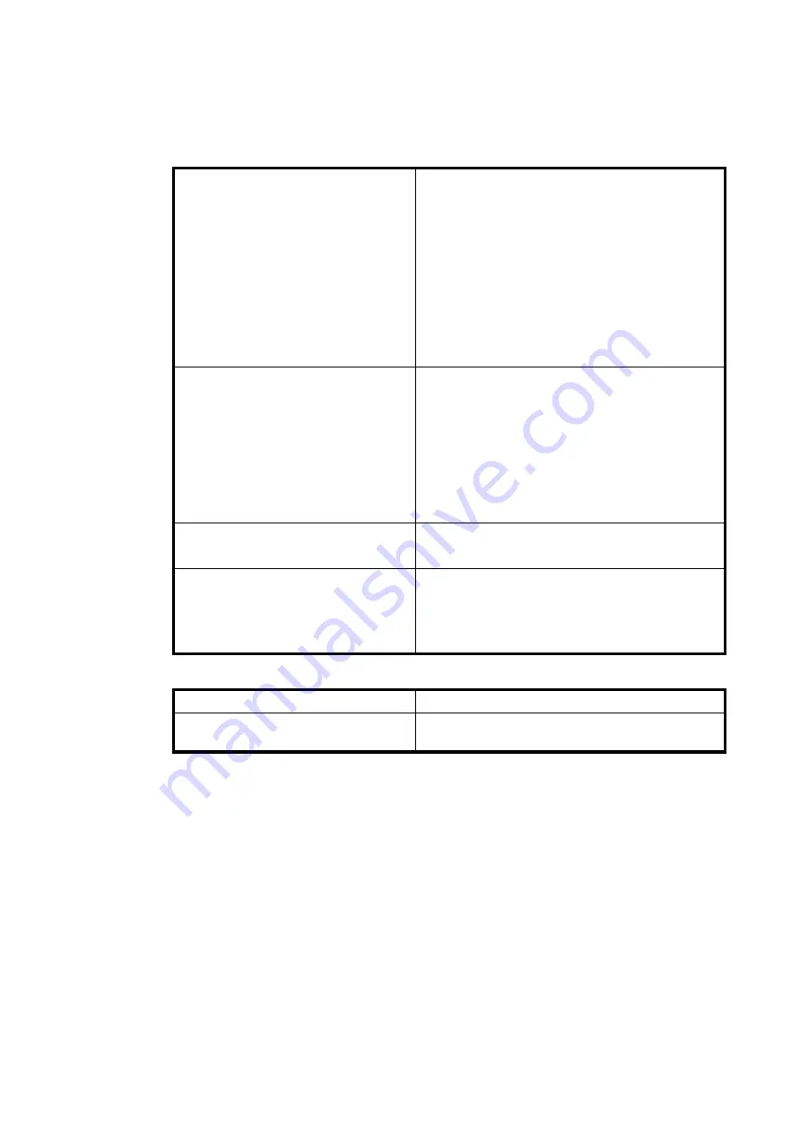
Input characteristics 

Input port 
Frequency range 
Max. input level 
Input destruction level 
Average noise level 
Resolution bandwidth (RBW) 


Input connector 


Two ports 
300 MHz to 6 GHz 
+0 dBm 
+10 dBm, DC 

±

 25 V 

RBW 1 kHz 

-70 dBm 

10 Hz to 15 kHz 

(1, 1.5, 2, 3, 4, 5, 7 steps) 
SMA (Female), 50 

Ω 

Amplitude characteristics 

Measurement range 

RBW 1 kHz 
Frequency response 

(At 0 dBm Input) 
Dynamic accuracy 

-20 dBm reference 


+0 dBm to -70 dBm 


10 dBp-p 


0 to -10 dBm 

1.0 dB 

-10 to -30 dBm   0.5 dB 

-30 to -50 dBm   1.5 dB 

Phase characteristic 

Measurement range 


±

180

° 

Error compensation function 

Transmission 


Reflection 


Normalization 

Transmission full calibration (short and load) 
1 port full calibration (open, short, and load) 

4.


Connection to External Devices 


External reference frequency input 

Input frequency 10 MHz 

±

 10 ppm > 0 dBm 

Parallel I/O 

8-bit output (3.3 V C-MOS) 

4-bit input (3.3 V C-MOS) 

Summary of Contents for R3755 Series

Page 1: ...5x R3760 Network Analyzer Operation Manual Manual Number FOE 8440279E06 Applicable Models R3755A R3755TF R3755E R3760 2009 ADVANTEST CORPORATION First Edition Oct 30 09 All Rights Reserved Printed in Japan ...

Page 2: ...d Registered Trademarks ADVANTEST is a trademark of Advantest Corporation Windows XP Windows Vista Windows 7 or Windows 10 is a trademark or registered trademark of Microsoft Corporation in the United States and other countries Visual C 6 0 Visual Basic 6 0 Visual Basic 2008 Visual C 2008 Visual Studio 2010 and NET Frame work are trademarks or registered trademarks of Microsoft Corporation in the ...

Page 3: ...Revision History Rev Date Notes A00 Oct 30 09 E05 Oct 26 18 E06 Mar 08 21 ...

Page 4: ...PANEL SURFACE Describes each part name and function on the panel 3 BAPI FUNCTIONS Describes the Application Programming Interface for Board Instruments BAPI functions 4 FUNCTION SPECIFICATIONS Describes the BAPI specification in detail 5 PERFORMANCE TEST Describes the performance check procedure 6 ADJUSTMENT Describes the reference frequency adjustment procedure 7 SPECIFICATIONS Provides the speci...

Page 5: ...3 3 3 4 CAL Types 3 3 3 3 5 Z Conversion Modes 3 4 3 3 6 Frequency Modes 3 4 3 3 7 Frequency Setting Types 3 4 3 3 8 IF AMP Modes 3 4 3 3 9 Analysis Channels 3 5 3 3 10 Port Numbers 3 5 3 3 11 Declaration of the Structure for BatchSetting 3 6 3 4 Error Code List 3 7 3 5 Packet Communication Functions Socket Communications 3 9 3 5 1 Communication Control Function List 3 9 3 5 2 BisOpenPacket 3 10 3...

Page 6: ...sCorrCollMeth 4 13 4 7 5 BisSensCorrColl 4 14 4 7 6 BisSensCorrCollSave 4 14 4 7 7 BisSensCorrCollDel 4 14 4 7 8 BisSensCorrCsetStat 4 15 4 7 9 QrySensCorrCsetStat 4 15 4 7 10 BisSensCorrCkitDefOpen 4 16 4 7 11 QrySensCorrCkitDefOpen 4 16 4 7 12 BisSensCorrCkitDefShor 4 16 4 7 13 QrySensCorrCkitDefShor 4 17 4 7 14 BisSensCorrCkitDefLoad 4 17 4 7 15 QrySensCorrCkitDefLoad 4 17 4 7 16 BisSensCorrCki...

Page 7: ... 4 10 2 QrySystErr 4 33 4 10 3 QrySystIden 4 33 4 11 TRACe Susbsystem 4 34 4 11 1 BisTracData 4 34 4 11 2 QryTracData 4 34 4 12 TRIGger Susbsystem 4 35 4 12 1 BisTrigSour 4 35 4 12 2 QryTrigSour 4 35 5 PERFORMANCE TEST 5 1 5 1 R3755A R3755TF R3755E Performance Test 5 1 5 1 1 Preparing for a Performance Test 5 1 5 1 2 General Cautionary Points 5 2 5 1 3 Frequency Accuracy and Range 5 2 5 1 4 Output...

Page 8: ...work Analyzer Control Server Window A 7 A 1 3 1 Descriptions of Window Components A 7 A 1 3 2 Selecting 10 MHz Standard A 9 A 1 3 3 Setting PI Circuit Connection Status A 10 A 1 4 Terminating Network Analyzer Control Server NACServer exe A 11 A 1 4 1 Procedure for Terminating NACServer exe A 11 A 1 4 2 Error Messages on Terminating NACServer exe A 11 A 1 4 3 Confirming Version Information A 12 A 1...

Page 9: ...C 5 A 3 1 13 MEAS A 33 A 3 1 14 Marker Function A 33 A 3 1 15 File F A 35 A 4 Dimensional OutlineDrawing A 36 ALPHABETICAL INDEX I 1 ...

Page 10: ... extension slot of a personal computer PC The key features of the analyzer are listed below The space saving automatic semiautomatic system can be easily configured Applications can be created and run on the PC Commercially available tools can be used This allows easy application development and maintenance A required driver is supplied as standard Wide measuring range 10 kHz to 300 MHz R3755A 10 ...

Page 11: ...rd Accessories List Name Model name Quantity Remarks R3755x R3760 Operation manual FOC 8440274 1 CD ROM SMA adapter SMASMAFM01 2 Parallel I O connector HDR E26MSG1 1 Parallel I O connector case HDR E26LPH1 1 1 3 Options Sold Separately The options used for the analyzer is shown below Options should be referred to by model name when ordered Table 1 2 Options Name Model name Highly stable standard f...

Page 12: ...is recommended to use a PC that is located in an environment with minimum line noise If line noise cannot be avoided attach a noise filter to the PC power supply An area allowing unobstructed air flow A cooling fan is located in the rear panel of the PC and vents are located in the side panels and on the bottom toward the front of the PC Never block the fan and these vents Keep the rear panel 10 c...

Page 13: ...t damage operate the analyzer within the specified input voltage Table 1 3 Power Supply Specifications R3755A R3755TF R3755E R3760 Required voltages 12 V 5 V 3 3 V 12 V 12 V 5 V 3 3 V 12 V Power consumption 15 W or lower 20 W or lower Keep the rear panel 10 centimeters away from the wall Do not use the analyzer upright turned the rear panel side down Front Use a noise cut filter when there is a la...

Page 14: ...erference using the following methods Change the direction of antenna of the television or the radio Place a PC with the R3755x R3760 installed away from any electrical devices such as TVs or radios Use a separate power supply to the power supply with electrical devices such as TVs orradios attached 5 Prevention of Electrostatic Buildup To prevent damages to semiconductor parts from electrostatic ...

Page 15: ... up When the analyzer temperature has reached room temperature turn on the PC and warm it up for at least 30 minutes Ground mat shoes Floor Equivalent resistance 106 to 109 Ω 1MΩ Benchboard Ground Method 3 Ground Method 2 Ground Method 1 Conductive mat Conductive mat 1MΩ Conductive mat Benchboard Copper foil tape 1MΩ Conductor Benchboard 1MΩ 1MΩ Benchboard ...

Page 16: ...erence frequency input connector Connect when using an external reference frequency Input frequency R3755A R3755TF 10 MHz 0 dBm or higher Input frequency accuracy R3755A R3755TF Within 10 ppm 2 1 3 Signal source output connector Outputs measurement signals 2 1 4 Receiver input connector Connects pass target signals 2 1 5 Parallel output connector Connects to a controller Refer to2 3 Input 4 bits O...

Page 17: ...rence value 2 2 2 External reference frequency input connector Connect when using an external reference frequency Input frequency 10 MHz 0 dBm or higher Input frequency accuracy Within 10 ppm 2 2 3 Measurement signal output port Outputs a measurement signal This can be used as a reflection mea surement port 2 2 4 Measurement signal input port Connects a measurement signal through adevice 2 2 5 Par...

Page 18: ...e port Caution Do not connect 23 Output port 3 C MOS level negative logic latch output 7 Maintenance port Caution Do not connect 10 Output port 4 C MOS level negative logic latch output 18 Maintenance port Caution Do not connect 22 Output port 5 C MOS level negative logic latch output 19 Maintenance port Caution Do not connect 9 Output port 6 C MOS level negative logic latch output 2 OPEN Do not c...

Page 19: ...R3760 must be executed in advance Controlling the R3755x R3760 from a user application program can be achieved by using the BAPI functions to communicate with the server program Winsock socket communications utilizing the TCP IP protocol is used to communicate between the user application program and the R3755x R3760 server program Figure 3 1 shown below shows the communication process between the...

Page 20: ...se calculations are also performed refer to Figure 3 2 For other formats calculations must be performed at application level using unformatted data Real Imag Port Raw data R input A input calculation R A A R Port1 input S11 S21 Port2 input Figure 3 2 Internal Data Flow data LOGMAG data PHASE data Parameter conversion Z Y l S Data Calibration data Error correction Normalization Full calibration Por...

Page 21: ...details refer to the error code 3 3 3 Measurement Ports Macro name Data Function BIS_MEAS_R 0x00000000 R CH port BIS_MEAS_A 0x00000001 A CH port BIS_MEAS_AR 0x00000010 A R CH port BIS_MEAS_S11 0x00000100 S11 port BIS_MEAS_S21 0x00000200 S21 port 3 3 4 CAL Types Macro name Data Function BIS_CAL_NORM 0x00000000 Normalization BIS_CAL_TRANS 0x00000001 Transmission full calibration BIS_CAL_1PORT 0x0000...

Page 22: ...ection BIS_CONV_YREFL 0x00000004 Admittance conversion reflection BIS_CONV_1DS 0x00000005 1 S Inverted S parameter 3 3 6 Frequency Modes Macro name Data Function BIS_FREQ_LIN 0x00000000 LIN mode BIS_FREQ_LOG 0x00000001 LOG mode 3 3 7 Frequency Setting Types Macro name Data Function BIS_FREQ_STRSTP 0x00000000 START STOP type BIS_FREQ_CNTSPN 0x00000001 CENTER SPAN type 3 3 8 IF AMP Modes Macro name ...

Page 23: ... BIS_TRAC1_UDT_IM 33 CH1 IMAG unformatted data BIS_TRAC1_LOGMAG 64 CH1 LOGMAG data BIS_TRAC1_LINMAG 65 CH1 LINMAG data BIS_TRAC1_PHASE 80 CH1 PHASE data BIS_TRAC1_CAL1 256 CH1 CAL data 1 complex data BIS_TRAC1_CAL2 257 CH1 CAL data 2 complex data BIS_TRAC1_CAL3 258 CH1 CAL data 3 complex data BIS_TRAC2_xxxx BIS_TRAC1_xxxx 1024 CH2 above CH1 value 1024 BIS_TRAC3_xxxx BIS_TRAC1_xxxx 2048 CH3 above C...

Page 24: ...Freq1 As Double CENTER frequency dblFreq2 As Double Frequency SPAN lngFtype As Long Frequency type 0 START STOP mode 1 CENTER SPAN mode lngFmode As Long Frequency mode BIS_FREQ_LIN orBIS_FREQ_LOG 0 LIN 1 LOG lngPntN As Long Number of measurement points sngRbw As Single RBW sngPow1 As Single Output level START sngPow2 As Single Output level STOP sngStime As Single Settling time End Type For Visual ...

Page 25: ...emelen parameter is too small or the name parameter related address has an incorrect address format ERR_WSAEINVAL 10022 The parameter s indicates a listening socket ERR_WSAEWOULDBLOCK 10035 The non blocking socket cannot be detected and the connec tion cannot be terminated immediately ERR_WSAEINPROGRESS 10036 The Windows socket 1 1 call for blocking is being processed Or the service provider is st...

Page 26: ...time limit to establish a connection has been exceeded ERR_WSAECONNREFUSED 10061 Client applications cannot be connected to the server because the amount of backlog in the server has reached the server limit ERR_WSANOTINITIALISED 10093 Call WSAStartup before using this function ERR_WSAEPARAMETER 10099 The set value is inapplicable to the R3760 FALSE 0x0001 Other errors ...

Page 27: ...ions are used in generating applications 1 BisOpenPacket When activating an application BisOpenPacket must be called to open a com munication path with the R3755x R3760 2 BisGetIpStr Acquires an IP address from the host name The acquired IP address is saved as a character string 3 BisClosePacket When terminating an application call BisClosePacket to close the communi cation path with the R3755x R3...

Page 28: ... 0 Indicates a normal termination A value other than 0 Indicates an error generation for details see 3 4 Error Code List Description TCP IP socket communications are opened and the packet ID is saved in the variable specified in lngPID Long BisOpenPacket must be executed before each BAPI function is executed Example For Visual Basic 6 0 Public Declare Function BisOpenPacket Lib bis dll _ ByVal str...

Page 29: ... Dim lngPID As Integer Private Sub cmdOpen_Click ByVal sender As System Object _ ByVal e As System EventArgs HandlescmdOpen Click Dim lngErr As Integer lngErr BisOpenPacket 127 0 0 1 0 lngPID Confirmation of successful connection If lngErr 0 Then MsgBox Invalid open the Communication Port Str lngErr _ vbOKOnly Else lngErr BisSystPres lngPID End If End Sub Private Sub BisOpenPacket_FormClosed ByVal...

Page 30: ...pAddr Example For 192 10 100 1 strIpAddr 192 10 100 1 Example For Visual Basic 6 0 Public Declare Function BisOpenPacket Lib bis dll _ ByVal strIP As String ByVal strBD As String ByRef lngPID As Long As Long Public Declare Function BisGetIpStr Lib bis dll _ ByVal strHost As String ByRef strIpAddr As String As Long Private Sub cmdOpen_Click Dim lngPID As Long Dim lngErr As Long Dim strIpAddr As Str...

Page 31: ...lngID As Integer As Integer Dim lngPID As Integer Private Sub cmdOpen_Click ByVal sender As System Object _ ByVal e As System EventArgs Handles cmdOpen Click Dim lngErr As Integer Dim strIpAddr As String lngErr BisGetIpStr ZeroOne strIpAddr lngErr BisOpenPacket strIpAddr lngPID Confirmation of successful connection If lngErr 0 Then MsgBox Invalid open the Communication Port Str lngErr _ vbOKOnly E...

Page 32: ...PID End Sub For Visual Basic 2008 Public Class BisClosePacket Public Declare Function BisOpenPacket Lib bis dll _ ByVal strIP As String ByVal strBD As String _ ByRef lngID As Integer As Integer Public Declare Function BisSystPres Lib bis dll _ ByVal lngPID As Integer As Integer Public Declare Function BisClosePacket Lib bis dll _ ByVal lngID As Integer As Integer Dim lngPID As Integer Private Sub ...

Page 33: ...3 5 4 BisClosePacket 3 15 Confirmation of successful connection If lngErr 0 Then MsgBox Invalid open the Communication Port Str lngErr _ vbOKOnly Else lngErr BisSystPres lngPID End If End Sub End Class ...

Page 34: ...nt in the API function lngID is defined separately as an external variable Place bis dll in a folder that can be recognized by Visual Basic Private Sub cmdSetup_Click Dim seg As SourSeg Call BisMeasAct lngID 1 Sets the measurement channel to CH1 seg dblFreq1 10 0e6 Sets the center frequency seg dblFreq2 1 0e6 Sets the frequency span seg lngFtype BIS_FREQ_CNTSPN Sets center and span settings mode s...

Page 35: ... As System Object ByVal e As System Even tArgs Handles cmdSetup Click Dim lngErr As Integer Dim segn As SourSeg lngErr BisMeasAct lngPID 1 Active CH Set segn dblFreq1 10000000 0 Center 10 MHz segn dblFreq2 1000000 0 Span 1 MHz segn lngFtype BIS_FREQ_CNTSPN Center Span Setting Type segn lngFmode BIS_FREQ_LIN Linear Frequency Type segn lngPntN 601 Measurement Points segn sngRbw 3000 0 RBW segn sngPo...

Page 36: ...urement channel Call QrySourSeg lngID seg 0 Calls stimulus settings Call QrySourSegCoun lngID Segcnt Calls the number of segments End Sub Program VB 2008 Adds MdlDeclare_bis vb and MdlBis_macro vb to the standard module in advance Assume the first argument in the API function lngID is defined separately as an external variable Place bis dll in a folder that can be recognized by Visual Studio Priva...

Page 37: ...otal measurement point number Calls the measurement result LOG amplitude Call QryTracData lngID BIS_TRAC1_LOGMAG 0 totP 1 logmag 0 End Sub Program VB 2008 Adds MdlDeclare_bis vb and MdlBis_macro vb to the standard module in advance Assume the first argument in the API function lngID is defined separately as an exter nal variable Place bis dll in a folder that can be recognized by Visual Studio Pri...

Page 38: ...ndP totP Calls the total measurement point number Call QrySensCorrCollMeth lngID caltype Calls the calibration type Calls each calibration data item Call QryTracData lngID BIS_TRAC1_CAL1 0 totP 1 cal1 0 Calibration data 1 Call QryTracData lngID BIS_TRAC1_CAL2 0 totP 1 cal2 0 Calibration data 2 Call QryTracData lngID BIS_TRAC1_CAL3 0 totP 1 cal3 0 Calibration data 3 End Sub Writing calibration data...

Page 39: ... measurement point number Call QrySensCorrCollMeth lngPID caltype Calls the calibration type Calls each calibration data item Call QryTracData lngPID BIS_TRAC1_CAL1 0 totP 1 cal1 0 Cal Data 1 Call QryTracData lngPID BIS_TRAC1_CAL2 0 totP 1 cal2 0 Cal Data 2 Call QryTracData lngPID BIS_TRAC1_CAL3 0 totP 1 cal3 0 Cal Data 3 End Sub Writing calibration data Private Sub cmdCalWrite_Click ByVal sender ...

Page 40: ...orces termination Argument IN long lngPID Packet ID specifies the value acquired by BisOpenPacket Return value Normal 0 BIS_TRUE or error 1 BIS_FALSE Description Measuring is reset If BisInitCont is set to OFF measurement is suspended If BisInitCont is set to ON the sweep is suspended and then restarts from the beginning A restart operation ...

Page 41: ...r error 1 BIS_FALSE Description Sets the Z conversion characteristic impedance 4 2 2 QryCalcTranImpCim Function name long QryCalcTranImpCimp Usage Reads the Z conversion characteristic impedance Argument IN long lngPID Packet ID specifies the value acquired by BisOpenPacket OUT double dblZ0 Characteristic impedance Ω Return value Normal 0 BIS_TRUE or error 1 BIS_FALSE Description QryCalcTranImpCim...

Page 42: ...ion admittance 5 Inverted S parameters Return value 0 Normal 1 The IngType argument is incorrectly specified Other Refer to Section 3 4 Error Code List Description Sets the Z conversion mode 4 2 4 QryCalcTranImpType Function name long QryCalcTranImpType Usage Reads the Z conversion mode Argument IN long lngPID Packet ID specifies the value acquired by BisOpenPacket OUT long lngType Z conversion mo...

Page 43: ...y corresponding to the position specified using the argument lng PntN is determined Then the value is stored in the argument dblFreq 4 3 2 QryFetcPoin Function name long QryFetcPoin Usage Acquires the point from frequency data Argument IN long lngPID Packet ID specifies the value acquired by BisOpenPacket long lngCh Specify CH 1 to 4 double dblFreq Specifies the frequency position used to convert ...

Page 44: ...n the value is stored in the variables specified using the arguments dblMaxV dblMaxF and lngMaxP respectively 4 3 4 QryFetcMin Function name long QryFetcMin Usage Acquires the minimum value in a specified range Argument IN long lngPID Packet ID specifies the value acquired by BisOpenPacket long lngTr Specifies the analysis channel BIS_TRACx_xxx long lngStrPnt The point where the search starts long...

Page 45: ...pecified using dblTgt is crossed is searched for in the range specified using the arguments lngStrPnt and lngStp Pnt Then the frequency and the left side point value and the right side point value of the crossed point are stored in the arguments of dblFreq lngPleft and lngPright respectively If lngStrPnt lngStpPnt the search direction is reversed 4 3 6 QryFetcVal Function name long QryFetcVal Usag...

Page 46: ...ine a measurement value OUT double dblValue Returns the measurement value Return value 0 Normal 1 The dblFreq argument is incorrectly specified Other Refer to Section 3 4 Error Code List Description The response value for the frequency position specified using the argument dblFreq is acquired Then the value is stored in the variable specified using the argument dblValue If the specified frequency ...

Page 47: ...sed to start measurement 4 4 2 QryInitCont Function name long QryInitCont Usage Reads continuous measurement continuity status ON or OFF Argument IN long lngPID Packet ID specifies the value acquired by BisOpenPacket OUT long lngOnoff 0 OFF 1 ON Return value Normal 0 BIS_TRUE or error 1 BIS_FALSE Description The continuous measurement continuity status ON or OFF set using BisInit Cont is read The ...

Page 48: ...StopP starts However long BistInitImm is disabled when BisInitCont is set to ON If the specified end point is larger than any of the measurement points the mea surement ends at the last measurement point 4 4 5 BisInitWai Function name long BisInitWai Usage Waits for the measurement to end Argument IN long lngPID Packet ID specifies the value acquired by BisOpenPacket Return value Normal 0 BIS_TRUE...

Page 49: ...upper or lower limit is specified Other Refer to Section 3 4 Error Code List Description An active channel 1 to 4 is set Measurement is performed and settings are made for the active channel 4 5 2 QryMeasAct Function name long QryMeasAct Usage Reads the active channel number Argument IN long lngPID Packet ID specifies the value acquired by BisOpenPacket OUT long lngCh CH number Return value Normal...

Page 50: ... 0 BIS_TRUE Error 1 BIS_FALSE Description Outputs the data specified for the lngData argument to the parallel outputport 4 6 2 QryPioIn Function name long QryPioIn Usage Inputs data from the parallel input port Negative logic Argument IN long lngPID Packet ID Specifies the value obtained by BisOpenPacket OUT long lngData Data to input Return value Normal 0 BIS_TRUE Error 1 BIS_FALSE Description In...

Page 51: ... Selects the standard kit for 1 port full calibration When UserDeinfe is specified the correction value specified using BisSen sCorrCkitUser becomes valid and the connector type is set to Female 4 7 2 QrySensCorrCkitType Function name long QrySensCorrCkitType Usage Reads the selected numbers of the standard kit for 1 port full calibration Argument IN long lngPID Packet ID specifies the value acqui...

Page 52: ...ion measurement BisSensCorrCsetStat was set to on Other Refer to Section 3 4 Error Code List Description A CAL type must be specified prior to acquiring CAL data Actual CAL data acquisition is performed using BisSensCorrColl This command is unavailable while BisSensCorrCsetStat is set to ON 4 7 4 QrySensCorrCollMeth Function name long QrySensCorrCollMeth Usage Reads the CAL type Argument IN long l...

Page 53: ...ied in advance using BisSensCorrCollMeth 4 7 6 BisSensCorrCollSave Function name long BisSensCorrCollSave Usage Calculates error factors Argument IN long lngPID Packet ID specifies the value acquired by BisOpenPacket Return value 0 Normal 5 BisSensCorrCollSave has already been executed 6 One of the calibration data has not been obtained Other Refer to Section 3 4 Error Code List Description Calcul...

Page 54: ...abled OFF 4 7 9 QrySensCorrCsetStat Function name long QrySensCorrCsetStat Usage Reads the calibration measurement status ON or OFF Argument IN long lngPID Packet ID specifies the value acquired by BisOpenPacket OUT long lngOnoff ON OFF Return value Normal 0 BIS_TRUE or error 1 BIS_FALSE Description The ON or OFF status set for the calibration measurement by using BisSen sCorrCsetStat is read The ...

Page 55: ... Packet ID specifies the value acquired by BisOpenPacket OUT double dblRs Impedance Rs Ω double dblLs Inductance Ls H double dblCp Capacitance Cp F Return value Normal 0 BIS_TRUE or error 1 BIS_FALSE Description Correction values set for the standard open circuit by using BisSensCorrCkit DefOpen are read and saved in variables dblRs dblLs and dblCp respec tively 4 7 12 BisSensCorrCkitDefShor Funct...

Page 56: ...ion values for the standard load Argument IN long lngPID Packet ID specifies the value acquired by BisOpenPacket double dblRs Specify impedance Rs Ω double dblLs Specify inductance Ls H double dblCp Specify capacitance Cp F Return value Normal 0 BIS_TRUE or error 1 BIS_FALSE Description Sets correction values for the standardload 4 7 15 QrySensCorrCkitDefLoad Function name long QrySensCorrCkitDefL...

Page 57: ...t loss double s11_short_imp SHORT offset Z0 double s11_res LOAD resistance double s11_load_delay LOAD offset delay double s11_load_loss LOAD offset loss double s11_load_imp LOAD offset Z0 c1ckit_t IN long lngPID Packet ID specifies the value acquired by BisOpenPacket long lngPORT Port number Refer to Section 3 3 10 Port Numbers ckit_t ckit Structure pointer long len Total number of bytes Return va...

Page 58: ...tance meters Argument IN long lngPID Packet ID specifies the value acquired by BisOpenPacket long lngFunc Measurement port Refer to Section 3 3 3 Measurement Ports double dblExtDist Electrical length correction values m Return value Normal 0 BIS_TRUE or error 1 BIS_FALSE Description Sets electrical length correction by distance dblExtDist unit is in meters Different data can be set for each measur...

Page 59: ...OFF for electrical length correction Argument IN long lngPID Packet ID specifies the value acquired by BisOpenPacket OUT long lngOnoff 0 OFF 1 ON Return value Normal 0 BIS_TRUE or error 1 BIS_FALSE Description ON OFF of the electrical length correction set by using BisSensCorrEdelStat is read The read value is stored in the lngOnoff variable 4 7 22 BisSensCorrEdelTime Function name long BisSensCor...

Page 60: ...t long lngFunc Measurement port Refer to Section 3 3 3 Measurement Ports double dblOffPhs Phase offset Degree Return value Normal 0 BIS_TRUE or error 1 BIS_FALSE Description Sets the phase offset unit degree specified using dblOffPhs Different data can be set for each measurement port A constant value is added to phase data Different from the electrical length correction the set value is always co...

Page 61: ...e offset ON OFF setting Argument IN long lngPID Packet ID specifies the value acquired by BisOpenPacket long lngOnoff 0 OFF 1 ON Return value Normal 0 BIS_TRUE or error 1 BIS_FALSE Description ON OFF of the phase offset set using BisSensCorrOffsStat isread The read value is stored in the lngOnoff variable 4 7 28 BisSensCorrPortExtDist Function name long BisSensCorrPortExtDist Usage Sets port exten...

Page 62: ...al 0 BIS_TRUE or error 1 BIS_FALSE Description Sets ON OFF for the measurement end face extension correction function Extension correction for the input port is performed While the electrical length is corrected for the set value this function performs correction for a value appropriate for the current input port by setting a corresponding value For example a reflection measurement having a value ...

Page 63: ...alue port extension unit sec onds Argument IN long lngPID Packet ID specifies the value acquired by BisOpenPacket long lngPortNo Port number 1 Port 1 2 Port 2 double dblExtTime Port extension correction value Sec Return value Normal 0 BIS_TRUE or error 1 BIS_FALSE Description The port extension correction value which is set for the port number specified by using the lngPortNo argument is read The ...

Page 64: ... 3 Measurement Ports double dblSlopPhs Phase slope Degree Return value Normal 0 BIS_TRUE or error 1 BIS_FALSE Description A phase slope Degree of dblSlopPhs is set for each port specified using lng Func Different data can be set for each measurement port A sloped phase value where the start point is 0 and the end point is the specified phase value is added to phase data This slope is linearly calc...

Page 65: ... R3760 0x0200 for S21 R3760 Return value 0 Normal 1 The IngFunc argument is incorrectly specified Other Refer to Section 3 4 Error Code List Description Specifies measurement ports Note For only R3760 the setting value differs 4 7 39 QrySensFunc Function name long QrySensFunc Usage Reads measurement port numbers Argument IN long lngPID Packet ID specifies the value acquired by BisOpenPacket OUT lo...

Page 66: ...mode The frequency mode BIS_FREQ_LIN or BIS_FREQ_LOG 0 LIN 1 LOG long lngPntN Specifies the number of measurementpoints float sngRbw Specifies IF RBW Hz float sngPow1 Specifies the START output level dBm float sngPow2 Specifies the STOP output level dBm float sngStime Specifies a settling time sec SourSeg IN long lngPID Packet ID specifies the value acquired by BisOpenPacket SourSeg Stim A structu...

Page 67: ...rray specified by using the argument Stim Note This command can specify up to 1601 segments in the R3755x R3760 Therefore set the array size to 1601 Secure a sufficiently sized array at the storage location argument Stim for the data placement No capacity check is conducted by the API function The memory data may be damaged if the array size differs 4 8 3 QrySourSegCoun Function name long QrySourS...

Page 68: ... resolution bandwidth set lngOnoff to ON and dblStime to 0 To end the automatic setting of a sweep time set lngOnoff to OFF and dblStime to an intended sweep time 4 8 5 QrySourSweTime Function name long QrySourSweTime Usage Reads the sweep time Argument IN long lngPID Packet ID specifies the value acquired by BisOpenPacket OUT long lngOnoff Specifies the enabled ON or disabled OFF status of TIME A...

Page 69: ...is set to 1601 Therefore it is recommended to provide the amount of memory for the maximum number 4 8 7 QrySourPowTab Function name long QrySourPowTab Usage Reads the output level table Argument IN long lngPID Packet ID specifies the value acquired by BisOpenPacket long lngCh Channel 1 to 4 OUT float fltPow An output level table for the number of measurement points Return value 0 Normal 1 The IngC...

Page 70: ...age Reads the table of segment info Argument IN long lngPID Packet ID specifies the value acquired by BisOpenPacket long lngCh Channel 1 to 4 OUT unsigned char chrBuff Table of segument info for the number of measurement points Return value 0 Normal 1 The IngCh argument is incorrectly specified Other Refer to Section 3 4 Error Code List Description Read the table of segment info for performing cal...

Page 71: ... measurement counter values Argument IN long lngPID Packet ID specifies the value acquired by BisOpenPacket OUT long lngEndP A measurement end point 0 to 1601 long lngTotP The total number of measurement points Return value Normal 0 BIS_TRUE or error 1 BIS_FALSE Description Measurement counter values are read The measurement end point data and the total number of measurement points which have been...

Page 72: ... Normal 0 BIS_TRUE or error 1 BIS_FALSE Description The most recent error number is read The read value is stored in the lngNo variable Error number 0 None 1 10 MHz Reference frequency reference cannot be detected 2 RF Synthe Unlock 3 LOCAL Synthe Unlock 4 Board temperature abnormality 4 10 3 QrySystIden Function name long QrySystIden Usage Reads system information Argument IN long lngPID Packet I...

Page 73: ...ray where Real data is saved first fol lowed by Imag data 4 11 2 QryTracData Function name long QryTracData Usage Reads specified trace data Argument IN long lngPID long lngTr Packet ID specifies the value acquired by BisOpenPacket Trace number Analysis channel specified with BIS_TRACx_xxx long lngStrP A start point 0 to 1600 long lngStpP An end point 0 to 1600 float fltBuff A data array pointer R...

Page 74: ...S_TRUE or error 1 BIS_FALSE Description If EXTERNAL is specified it waits for an input from the parallel input A trigger occurs when the input signal from a parallel input matched the pattern setting 4 12 2 QryTrigSour Function name long QryTrigSour Usage Reads the trigger source Argument IN long lngPID Packet ID specifies the value acquired by BisOpenPacket OUT long lngTrig Trigger source long ln...

Page 75: ...nstruments for Performance Test Test items Measurement instrument Remarks 1 Frequency accuracy and range Counter Frequency 1 MHz to 300 MHz Display 7 digits or more Accuracy 0 1ppm or less Refer to section 5 1 3 BNC SMA cable 2 Output Input level and flatness Power meter Frequency 1 MHz to 300 MHz Power range 43 dBm to 21 dBm Refer to section 5 1 4 Power sensor Frequency 1 MHz to 300 MHz Power ran...

Page 76: ...55x as shown in the figure below To counter input Figure 5 1 Frequency Accuracy and Range 4 Set the R3755x as follows Span 0 Hz Sweep mode SINGLE 5 Change the center frequency to the desired setting within the following ranges R3755A 10 kHz to 300 MHz R3755TF 10 kHz to 10 MHz R3755E 1 MHz to 300 MHz 6 Check that the counter read frequency center frequency center frequency 20 10 6 Example When the ...

Page 77: ...55x as follows PI circuit ON Center frequency 10 MHz Span 0 Hz Output level 0 dBm 10 Connect the power sensor to the output terminal and perform themeasurement NOTE The calibration factor should be set to 10 MHz 11 Check the output level accuracy of 2 0 dB at 0 dBm and 10 MHz Flatness 12 Perform the ZERO calibration for the power meter 13 Set the R3755x as follows PI circuit ON Center frequency 10...

Page 78: ...g procedure 17 Perform the ZERO calibration for the power meter 18 Set the R3755x as follows PI circuit ON Center frequency 10 MHz Span 0 Hz Output level 0 dBm 19 Connect the power sensor to the output terminal as shown in the figurebelow Figure 5 3 Output Level Linearity 20 Press the REL key on the power meter and set it to 0 dB ratio test mode 21 Obtain the linearity data when the output level i...

Page 79: ...5E 1 MHz R3755TF 10 kHz Stop frequency R3755A R3755E 100 MHz R3755TF 10 MHz Resolution band width R3755A R3755TF R3755E 1 kHz 26 Sweep the frequency once using the SINGLE sweep mode Sum up the results of measurement data from the first point to the 1601th point and divide it by 1601 Noise floor MEAS 1 MEAS 2 MEAS 1601 1601 MEAS n the measurement data at the nth point 27 Check The noise floor dBm 8...

Page 80: ...evel accuracy of magnitude characteristics Testing Procedure Dynamic Level Accuracy 29 Connect the 3 dB fixed attenuator and step attenuator to OUTPUT and INPUT respectively by using the RF cables as shown in the figure below Figure 5 4 Dynamic Level Accuracy 30 Set PI circuit to OFF center frequency to 11 MHz for R3755A or 9 MHz for R3755TF frequency span to 0 Hz output power to 6 dBm and RBW to ...

Page 81: ... 3 dB 50 dB 0 3 dB 60 dB 0 5 dB Confirm Confirm that dynamic level accuracy is within the standard values of the above table for the various step attenuator setting values Dynamic level accuracy marker reading value step attenuator value CAUTION Use a value calibrated from a 20 dB standard as the step attenuator value When 19 95 dB is calibrated as the difference from 20 dB at a setting of 0 dB th...

Page 82: ... Test Test items Measurement instrument Remarks 1 Frequency accuracy and range Counter Frequency 100 MHz to 6 GHz Display 7 digits or more Accuracy 0 1ppm or less Refer to section 5 2 3 SMA SMA cable 2 Output Input level and flatness Power meter Frequency 100 MHz to 6 GHz Power range 20 dBm to 10 dBm Refer to section 5 2 4 Power sensor Frequency 100 MHz to 6 GHz Power range 43 dBm to 21 dBm 3 Outp...

Page 83: ...y and Range Testing procedure 3 Setup the R3760 as shown in the figure below To counter input Figure 5 5 Frequency Accuracy and Range 4 Set the R3760 as follows Span 0 Hz Sweep mode SINGLE 5 Change any center frequency in the range of 300 MHz to 6 GHz 6 Check that the counter read frequency center frequency center frequency 50 10 6 Example When the center frequency is at 1 GHz the range is 1 GHz 5...

Page 84: ...3760 as follows Center frequency 1 GHz Span 0 Hz Output level 0 dBm 10 Connect the power sensor to the output terminal and perform themeasurement NOTE The calibration factor should be set to 1 GHz 11 Check the output level accuracy of 2 0 dB at 0 dBm and 1 GHz Flatness 12 Perform the ZERO calibration for the power meter 13 Set the R3760 as follows Center frequency 1 GHz Span 0 Hz Output level 5 dB...

Page 85: ...nearity Testing procedure 17 Perform the ZERO calibration for the power meter 18 Set the R3760 as follows Center frequency 1 GHz Span 0 Hz Output level 0 dBm 19 Connect the power sensor to the output terminal as shown in the figurebelow Figure 5 7 Output Level Linearity 20 Press the REL key on the power meter and set it to 0 dB ratio test mode 21 Obtain the linearity data when the output level is ...

Page 86: ...ment points 1601 Format LOGMAG MEAS S21 25 Set the frequency range and the resolution band width as follows Start frequency 300 MHz Stop frequency 6 GHz Resolution band width 1kHz 26 Sweep the frequency once using the SINGLE sweep mode Sum up the results of measurement data from the first point to the 1601th point and divide it by 1601 27 Check The noise floor dBm 70 dBm ...

Page 87: ...mic level accuracy of magnitude characteristics Testing Procedure Dynamic Level Accuracy 28 Connect the fixed attenuator and step attenuator to PORT1 and PORT2 respectively by using the RF cables as shown in the figure below Figure 5 8 Dynamic Level Accuracy 29 This operation sets Center Frequency to 1 GHz Frequency Span to 0 Hz Output power to 5 dBm and RBW to 30 Hz 30 Set the step attenuator to ...

Page 88: ... 5 dB 50 dB 1 5 dB Confirm Confirm that dynamic level accuracy is within the standard values of the above table for the various step attenuator setting values Dynamic level accuracy marker reading value step attenuator value CAUTION Use a value calibrated from a 20 dB standard as the step attenuator value When 19 95 dB is calibrated as the difference from 20 dB at a setting of 0 dB the step attenu...

Page 89: ... To counter input Figure 6 1 Frequency Reference Adjustment R3755A R3755TF with OPT20 2 Set the R3755x as follows Center frequency 10 MHz Span 0 MHz Sweep mode SINGLE Output level 0 dBm 3 Adjust the STD ADJ volume so that the counter read frequency is within the fol lowing range Adjustment range 9 999 992 to 10 000 008 0 8 ppm R3755A R3755TF STD ADJ volume ...

Page 90: ...the figure below To counter input Figure 6 2 Frequency Reference Adjustment R3760 with OPT20 2 Set the R3760 as follows Center frequency 1 GHz Span 0 MHz Sweep mode SINGLE Output level 0 dBm 3 Adjust the STD ADJ volume so that the counter read frequency is within the fol lowing range Adjustment range 999 999 200 Hz to 1000 000 800 Hz 0 8 ppm STD ADJ volume ...

Page 91: ...m Opt20 Output characteristics PI circuit ON Range 0 dBm to 30 dBm 10 kHz to 1 MHz 18 dBm to 43 dBm 1 MHz to 300 MHz Resolution 0 1 dB Accuracy 2 0 dB 0 dBm 10 MHz Linearity 10 MHz 18 dBm to 35 dBm 1 5dB 35 dBm to 43 dBm 2 5 dB Flatness At 0 dBm Output 1 MHz to 100 MHz 5 0 dBp p 100 MHz to 300 MHz8 0 dBp p Sweep characteristics Sweep parameter Frequency Range Frequency sweep same as frequency char...

Page 92: ... dBm to 70 dBm Frequency response At 0 dBm Input 10 kHz to 1 MHz 10 0 dBp p 0 dBm input and output connection Ach measurement 1 MHz to 100 MHz 6 0 dBp p 100 MHz to 300 MHz 8 0 dBp p Dynamic accuracy 20 dBm reference 0 to 10 dBm 0 5 dB 10 to 50 dBm 0 3dB 50 to 60 dBm 0 5dB Phase characteristic Measurement range 180 Error compensation function Normalize Transmission full calibration Frequency respon...

Page 93: ...rature range Humidity range Refer to the PC s specification Maximum temperature range 5 to 55 C 2 Refer to the PC s specification Maximum range 80 No moisture Storing environment Temperature range Humidity range 20 C to 60 C Maximum 85 No moisture Power supply DC 12 V 1 W 5 V 5 W 3 3 V 5 W and 12 V 1 W Major voltages Supplied through PCI connector Power consumption 15 Watt or lower Dimensions Appr...

Page 94: ...ics Range Resolution Accuracy 10 kHz to 10 MHz 1 mHz 20 ppm 1 ppm Opt20 Output characteristics Range 0 dBm to 30 dBm Resolution 0 1 dB Accuracy 2 0 dB 0 dBm 10 MHz Linearity 10 MHz 0 dBm to 30 dBm 1 5 dB Flatness At 0 dBm Output 5 0 dBp p Sweep characteristics Sweep parameter Frequency Range Frequency sweep same as frequency characteristics Range setting Start Stop or Center Span Sweep type Any sp...

Page 95: ...dBm Input Dynamic accuracy 20 dBm reference 0 dBm to 70 dBm 0 dBm input and output connection Ach measurement 6 0 dBp p 0 to 10 dBm 0 5 dB 10 to 50 dBm 0 3dB 50 to 60 dBm 0 5dB Phase characteristic Measurement range 180 Error compensation function Normalize Transmission full calibration Frequency response compensation Amplitude and phase for transmission measurement Highly accurate measurement tha...

Page 96: ...ature range Humidity range Refer to the PC s specification Maximum temperature range 5 to 55 C 2 Refer to the PC s specification Maximum range 80 No moisture Storing environment Temperature range Humidity range 20 C to 60 C Maximum 85 No moisture Power supply DC 12 V 1 W 5 V 5 W 3 3 V 5 W and 12 V 1 W Major voltages Supplied through PCI connector Power consumption 15 Watt or lower Dimensions Appro...

Page 97: ...solution 1 Hz Accuracy 50 ppm Output characteristics Range 5 dBm to 10 dBm Resolution 1 dB Flatness At 0 dBm Output 8 0 dBp p Sweep characteristics Sweep parameter Frequency Range Frequency sweep same as frequency characteristics Range setting Start Stop or Center Span Sweep type Any specified segment sweep Frequency Output level RBW Point Settling setting Sweep time Max 0 05 ms Point RBW 15 kHz M...

Page 98: ...z 85 dBm 70 dBm Resolution bandwidth RBW 10 Hz to 15 kHz 1 1 5 2 3 4 5 7 steps Input connector SMA Female 50 Ω Amplitude characteristics Measurement range RBW 1 kHz 1 MHz to 100MHz 0 dBm to 85 dBm 100 MHz 0 dBm to 70 dBm Frequency response At 0 dBm Input 1 MHz to 300 MHz 8 0 dBp p 0 dBm input output connection Error compensation function Normalize Correcting frequency response amplitude when trans...

Page 99: ...rature range Humidity range Refer to the PC s specification Maximum temperature range 5 to 55 C 2 Refer to the PC s specification Maximum range 80 No moisture Storing environment Temperature range Humidity range 20 C to 60 C Maximum 85 No moisture Power supply DC 12 V 1 W 5 V 5 W 3 3 V 5 W and 12 V 1 W Major voltages Supplied through PCI connector Power consumption 15 Watt or lower Dimensions Appr...

Page 100: ...ution Accuracy 300 MHz to 6 GHz 10 kHz 50 ppm Output characteristics Range Resolution Accuracy Linearity 1 GHz Flatness At 0 dBm Output 3 GHz 0 dBm to 10 dBm 3 GHz 5 dBm to 10 dBm 0 1 dB 2 0 dB 0 dBm 1 GHz 0 dBm to 10 dBm 1 5 dB 300 MHz to 1 GHz 8 0 dBp p 1 GHz to 4 GHz 6 0 dBp p 1 GHz to 6 GHz 8 0 dBp p Sweep characteristics Sweep parameter Range Range setting Sweep type Sweep time Measurement po...

Page 101: ...0 Ω Amplitude characteristics Measurement range RBW 1 kHz Frequency response At 0 dBm Input Dynamic accuracy 20 dBm reference 0 dBm to 70 dBm 10 dBp p 0 to 10 dBm 1 0 dB 10 to 30 dBm 0 5 dB 30 to 50 dBm 1 5 dB Phase characteristic Measurement range 180 Error compensation function Transmission Reflection Normalization Transmission full calibration short and load 1 port full calibration open short a...

Page 102: ...the PC s specification Maximum temperature range 5 to 55 C 2 Refer to the PC s specification Maximum range 80 No moisture Storing environment Temperature range Humidity range 20 C to 60 C Maximum 85 No moisture Power supply DC 5V 6W 3 3V 9W 12V 1 1W 12V 0 5W Major volt ages Supplied through PCI connector Power consumption Maximum 20 Watt Dimensions Approximately 190 W 126 H 42 D mm Mass 1 kg or le...

Page 103: ...ts such as benzene toluene xylene acetone or similar compounds since these solvents may damage the plastic parts 3 Do not use cleanser 8 2 Calibration and Repair Calibration and repair work should be performed at an Advantest Corporation site For calibrating and repairing this instrument contact Advantest 8 3 Storing Store the analyzer in an area which has a temperature from 20 C to 60 C If you pl...

Page 104: ...r on all sides with packing material 4 Seal the corrugated cardboard container with shipping tape or an industrial stapler CAUTION Precautions for Transportation Do not transport this instrument while it is installed inside a personal computer Vibration during transportation may damage the instrument If you are shipping the analyzer to Advantest for service or repair attach a tag to the analyzer t...

Page 105: ...81 Connectors inductors resistors diodes semiconductor packages Asbestos waste and components which contain asbestos Not used Cathode ray tubes Not used Chlorofluorocarbons CFC Hydro chlorofluorocarbons HCFC Hydro fluorocarbons HFC or Hydrocarbons HC Not used Gas discharge lamps Not used Liquid crystal displays of a surface greater than 100 square centimeters and all those back lighted with gas di...

Page 106: ...tance Component Used Not used Location Parts and material Arsenic and Arsenic compounds Used BPC 036279 Electronic components Semicon ductors Lead and Lead compounds Used BPC 036279 BEC 036681 Electronic components Vinyl chloride PVC Not used ...

Page 107: ...tallation may take time depending on PC used Do not perform any operation until the Finish button of the installer is displayed When using a laptop computer connected via PCI BUS external I F driver installation is required When uninstalling uninstall NACServer from the program delete function on the WindowsCon trol Panel After it has been uninstalled restart the PC b Sample application program in...

Page 108: ... the Microsoft website To delete R3755x or R3760 programs from the computer execute the following a When deleting NACServer uninstall NACServer from the program delete function on the Windows Control Panel After it has been uninstalled restart the PC b When deleting a sample application program uninstall the desired sample application program from the program delete function on the Windows Control...

Page 109: ...ogram Start the server program by using the following procedure 1 The contents of the C Program Files ADVANTEST NACServer folder in the host PC are as shown in Figure A 1 Double click NACServer exe server program in this folder Figure A 1 R3755x R3760 Folder Window 2 The following window is displayed If this window is displayed and an error message is not displayed the R3755x R3760 started correct...

Page 110: ...g R3755x R3760 The following error messages may occur when NACServer exe starts NACServer double activation error Figure A 3 Double Activation Error Message R3755x R3760 a R3755x R3760 connection error b R3755x R3760 10MHz Reference detection error c R3755x R3760 temperature error ...

Page 111: ...tly b Win Driver is not installedcorrectly c The TCP IP protocol is not installed For this error the following two messages are displayed For the R3755x R3760 those two messages are displayed in a set every time this error occurs Clicking OK in the error message 1 window displays the error message 2 window Clicking OK in the error message 2 window displays the R3755x R3760 startup window Figure A ...

Page 112: ...ted 10MHz Reference cannot be detected while starting the R3755x R3760 Figure A 6 10MHz Reference detection error A 1 2 4 R3755x R3760 Temperature Error This error occurs when the board temperature becomes abnormal Figure A 7 Temperature Error CAUTION Disable the Hibernate status in the Internet Option Properties of the PC setting ...

Page 113: ...ns of Window Components 3 1 2 Figure A 8 R3755x R3760 Window 1 10MHz standard selection button INT EXT and OPT20 2 π circuit selection button ON or OFF Always select OFF when a π circuit jig is not used R3755x When switching to ON or OFF the following message is displayed 3 NACServer exe quit button Clicking this button terminates NACServer exe ...

Page 114: ...ows only the recognized number of boards Each titled field in this area shows the following information 0 to 7 R3755x R3760 board number Instrument Name of the instrument Serial No R3755x R3760 board serial number Hardware Hardware information required for maintenance work 10MHz Ref 10 MHz standard selection status PI circuit π circuit selection status R3755A R3755TF 6 Error status indication area...

Page 115: ...d can be selected by using the following procedure 1 Clicking the button indicated by a board number from 0 to 7 on the cor responding board shown in Figure A 8 for 10MHz Ref displays a pull down menu showing selectable frequency standards NOTE If selecting EXT or OPT20 verify that the necessary frequency standard has been provided If the necessary frequency standard has not been provided an error...

Page 116: ... connecting PI Circuit OFF Set OFF when not connecting PI Circuit Set the PI circuit connection status by using the following procedure 1 Clicking the button indicated by a board number from 0 to 7 on the cor responding board shown in Figure A 8 for PI Circuit displays a pull down menu showing PI circuit connection status 2 Select ON or OFF depending on the PI circuit connection status ...

Page 117: ...er window The following message window is displayed Figure A 11 Message on Terminating 2 To terminate it click the Yes Y button A 1 4 2 Error Messages on Terminating NACServer exe 3 If the NACServer exe is terminated while an application program is being con nected to Network Analyzer Control Server the following message is displayed Figure A 12 Error Message 1 on Terminating 4 Clicking the OK but...

Page 118: ...ing the Yes Y button continues the termination process In this case also terminate the application program A 1 4 3 Confirming Version Information 6 Right clicking on the title bar see 4 in Figure A 10 of the Network Analyzer Control Server window opens a menu as shown below Figure A 14 Version Information Confirmation Window 7 From the menu select About NACServer A The following message window is ...

Page 119: ...dlBis_macro vb Macro definitions for VB 2008 Const declarations MdlDeclare_bis vb Function definitions for VB 2008 Declare declarations When Visual Basic 6 0 is used Copy bis dll inside the samefolder Add declare_bis bas to the standard module Add bis_macro bas to the standard module When Visual Basic 2008 is used Copy bis dll inside the folder in which Exe is generated Open the project file of Vi...

Page 120: ...ration is unneces sary 5 Click the Connect button in the Connection Box area of the sample program window If a waveform is displayed on the sample program window after the above steps 1 to 5 are performed the sam ple program is now enabled If a waveform is not displayed verify the BD or IP value specified in step 4 and correct the value as required Click the Connect button in the Connection Box ar...

Page 121: ...al Kit Ele Corr and Func Display scale setting area Sets the scale for LOGMAG PHASE DELAY SWR REAL and IMAG In addition whether to display PHASE can be selected Stimulus Sets the frequency range to be swept number of sweep points power level settling time and other settings for the signal source and the resolution bandwidth RBW for the receiver Setting area for other measurement items Sets the cha...

Page 122: ...ns Sets marker addition Add deletion Del marker search Max Min 0 phase marker center frequency Port Extension tracking and Compensate ON OFF File F Reads from or saves to a file the Read O Save S measurement sta tus Read O sets Stimulus when connection has been established with the Connect button and the same model setting is used Save S saves data for the currently displayed CH NOTE 1 Read O sets...

Page 123: ... may occur depending on the environment Cal Calibration status FREQUENCY Marker frequency LOGMAG LOGMAG marker read value PHASE PHASE marker read value LINMAG LINMAG marker read value A 3 1 2 Reset Button Figure A 19 Reset Button Initializes R3755x R3760 settings A 3 1 3 Measurement Channel Setting Figure A 20 Measurement Channel Display Four fully independent measurement channels from CH1 to CH4 ...

Page 124: ...mation Cont Clicking this button executes sweeps successively Hold Abort Clicking this button immediately terminates the sweep Single Clicking this button executes a single sweep If this button is clicked during a sweep the measurement being swept is stopped and the sweep is started again Part If this check box is selected a sweep is partially executed A sweep is executed in a range according to t...

Page 125: ...24 Stimulus Settings LOGMAG Sets the LogMag waveform scale PAHSE Sets the Phase waveform scale Stimulus Sets measurement conditions CAL Sets and executes calibration Trace data saving to memory Saves or clears trace data and sets the display ON OFF For more information refer to the following Appendix 3 1 7 Display Scale Setting Area Appendix 3 1 8 Stimulus Appendix 3 1 9 Setting Area for Other Mea...

Page 126: ...ypes are as follows Don t Care No selection User Define Uses user specific calibration values 3 5mm Uses calibration values of the MAURY produced CAL Kit 3 5mm R S Uses calibration values of the ROHDE SCHWARZ produced CAL Kit User Define Sets specific calibration data correction values in the following win dow Figure A 25 User CAL DATA ...

Page 127: ...e Assuming that a completely lossless cable has been added electrical length for the addition is corrected By correcting the phase shift for the extension phase characteristics for the sample can be obtained Electrical length correction Electrical Delay The electrical length set to measurement data is corrected Any measurement port can be used This function can be used when measuring cable electri...

Page 128: ...trical length The initial value is 1 Phase correction amount deg L φ S f 360 θ f 360 θ vf c S Electrical length correction value time f Frequency at each measurement point L Electrical length correction value distance vf Velocity factor θ Phase offset c Speed of light Func Figure A 27 Analysis Function Area ...

Page 129: ...ce between maximum and minimum is greater than the specified value the waveform is measured as a ripple Max freq point Displays the frequency point at the ripple maximum point Max level Displays the level at the ripple maximum point Min freq point Displays the frequency point at the ripple minimumpoint Min level Displays the level at the ripple minimum point RplSearch Executes a ripple search Disp...

Page 130: ... performed at a frequency much lower than the resonant frequency using Seg0 In this example 9 MHz is specified for C0 freq MHz EquCkt4 Measures the equivalent constant of fourelements EquCkt4CH Measures the equivalent constant of fourelements Before equivalent constant measurement the frequency is read and admittance conversion is performed each time The measurement time slightly increases compare...

Page 131: ... graph display CI ohm Sets the CI graph display F Hz Sets F graph Start dBm Sets a DLD measurement start level Stop dBm Sets a DLD measurement stop level Points Sets the number of DLD measurement points RBW Hz Sets RBW for DLD measurement Settling ms Sets device response time for DLD measurement Typ CI Ω Sets the impedance for the DLD measurement target device NOTE Electric power is calculated by ...

Page 132: ...nary part Figure A 31 LOGMAG PHASE DELAY SWR REAL IMAG Each titled field sets the following information LOGMAG DELAY SWR REAL IMAG When LOGMAG is displayed the display is the logarithmic ampli tude scale When DELAY is displayed the display is the group delay scale When SWR is displayed the display is the standing wave ratio scale When REAL is displayed the display is the real number scale When IMA...

Page 133: ...le When segments have been set from 0 to 5 the seg ment that can be deleted is only segment 5 If it is nec essary to delete segments 1 to 5 delete them one by one in descending order from 5 Start Specify a start frequency for sweep Stop Specify a stop frequency for sweep Cent Specify a center frequency for sweep Span Specify a frequency span for sweep Select a span input unit from the drop down me...

Page 134: ...Each titled field sets the following information MemoNo Sets a number to be saved to memory 1 to 3 Save Clr Clears the memory saving status Save Sv Saves to memory Disp ON OFF Sets ON OFF for the display of data saved in memory Z0 Specifies characteristic impedance with a numeric value Conv Selects a parameter conversion condition from the drop down menu The selectable items are as follows OFF Doe...

Page 135: ... this button calibrates frequency characteristics of ampli tude and phase This calibration method is referred to as normalization clear Clicking this button clears calibration data The previous calibration data must be cleared when calibration is executed again However if normalization is executed it can be made without clear ing the previous calibration data Method Select a calibration method fro...

Page 136: ...of Window Components A 30 A 3 1 11 Trace Waveform Format Selection A measurement waveform format can be selected LogMag waveform POLAR waveform Smith waveform DELAY waveform Figure A 35 Measurement Waveform Formats 1 of 2 ...

Page 137: ...A 3 1 Descriptions of Window Components A 31 SWR waveform REAL waveform IMAG waveform Overlap waveform Figure A 35 Measurement Waveform Formats 2 of 2 ...

Page 138: ...at By selecting the Overlap tab different formats are displayed simultaneously When Overlap is selected the following Overlap Format check boxes are enabled Figure A 36 Overlap Format By selecting each check box trace waveforms are displayed Figure A 37 Overlap Screen ...

Page 139: ...f S11 or S21 A 3 1 14 Marker Function Figure A 39 Marker Settings associated with the marker can be made Each titled field sets the following information Marker check box Sets ON OFF for the marker display Active Mkr text box Enter the displayed active markernumber buttons Selects an active marker number Frequency text box Moves to the frequency at the measurement point closest to the specified fr...

Page 140: ...he active marker 0 deg button Searches for the point where the phase is 0 degrees and displays it by the active marker Cent button Sets frequency using the marker frequency as the center frequency PEXT button Performs marker to port extension Check box above Max button Searches and displays the maximum value for each sweep Check box above Min button Searches and displays the minimum value for each...

Page 141: ... conditions and waveform data can be saved to a file Also a saved file can be read using the Read menu item The Save menu item saves data in CSV format text The Read menu item reads measurement conditions from a saved file and sets them to the R3755x R3760 NOTE The Read menu item can read and display data even on a PC without theR3755x R3760 ...

Page 142: ...line Drawing R3755x DIMENSIONAL OUTLINE DRAWING R3755x 外 形寸法図 R3755x DIMENSIONAL OUTLINE DRAWING Unit mm NOTE This drawing shows external dimensions of this instrument The difference in products and options used can cause a change in the appearance of the instrument ...

Page 143: ...omponents A 37 R3760 DIMENSIONAL OUTLINE DRAWING 外形寸法図 R3755x Unit mm NOTE This drawing shows external dimensions of this instrument The difference in products and options used can cause a change in the appearance of the instrument ...

Page 144: ...justment R3760 with OPT20 6 2 A 1 R3755x R3760 Folder Window A 3 A 2 R3755x R3760 Startup Window A 3 A 3 Double Activation Error Message A 4 A 4 Error Message 1 A 5 A 5 Error Message 2 A 5 A 6 10MHz Reference detection error A 6 A 7 Temperature Error A 6 A 8 R3755x R3760 Window A 7 A 9 R3755x R3760 Window A 8 A 10 Frequency Standard Selection Window A 9 A 11 Message on Terminating A 11 A 12 Error ...

Page 145: ...tion A 25 A 31 LOGMAG PHASE DELAY SWR REAL IMAG A 26 A 32 Stimulus A 27 A 33 Measurement Item Setting Area A 28 A 34 CAL A 29 A 35 Measurement Waveform Formats 1 of 2 A 30 A 36 Overlap Format A 32 A 37 Overlap Screen A 32 A 38 Meas A 33 A 39 Marker A 33 A 40 Marker Display Screen A 34 A 41 File F A 35 ...

Page 146: ...ables 1 1 Standard Accessories List 1 2 1 2 Options 1 2 1 3 Power Supply Specifications 1 4 5 1 Required Measurement Instruments for Performance Test 5 1 5 2 Required Measurement Instruments for Performance Test 5 8 ...

Page 147: ...3 7 Error Messages on Starting R3755x R3760A 4 Error Messages on Terminating NACServer exe A 11 EXPLANATION OF PANEL SURFACE 2 1 Explanation of Sample Programs A 15 F FETCh Subsystem 4 4 File F A 35 Frequency Accuracy and Range 5 2 5 9 Frequency Modes 3 4 Frequency Reference Adjustment R3755A R3755TF with OPT20 6 1 Frequency Reference Adjustment R3760 with OPT20 6 2 Frequency Setting Types 3 4 Fro...

Page 148: ...6 R3760 Performance Test 5 8 R3760 Specifications 7 10 Required Measurement Instruments for Performance Test 5 1 5 8 Reset Button A 17 S Selecting 10 MHz Standard A 9 SENSe Subsystem 4 12 Setting Area for Other Measurement Items A 28 Setting Conditions for an Instrument 3 16 Setting PI Circuit Connection Status A 10 SOURce Subsystem 4 27 SPECIFICATIONS 7 1 Starting R3755x R3760 A 1 STATus Subsyste...

Reviews: