73
Appendix B
B.2 Open Loop Motion Control (Pulse Command)
PC Controller sends commands to the PCI BUS interface circuit (4) on
PCI-1241/1242 card through PCI BUS (1). At this time, the command
and state register (5) with system control circuit (8) will decode com-
mands and enable DDA generator (9) in the driver to send out pulses
evenly (selectable to A/B PHASE, CW/CCW, and PULSE/DIRECTION
formats). Pulses are then sent to external motor drivers of pulse-type
servo motor/stepping motor (11) through line driver (10) (MC3487) in
the form of differential signal. If there is a need, the motor encoder (12)
signal could be feedback to command and state register (5) through photo
coupler isolator (20) and then entering encoder interface (19) for CPU to
read.
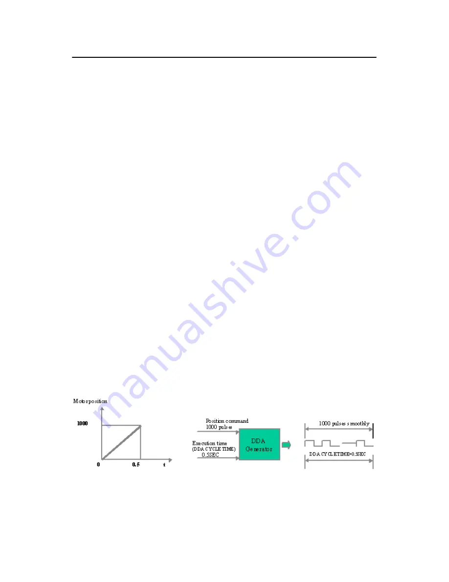
B.2.1 Digital Differential Analyzer (DDA)
DDA generator receives the position command from CPU (i.e. the
required rotation quantity of pulse for the motor) and time required to
execute the command (defined as DDA CYCLE TIME). After calcula-
tion, DDA generator could send out the pulse required evenly within
DDA cycle.
For instance (refer to Figure B-2), assuming the starting position for
motor is at 0. When the position command is positive rotation of 1000
pulses, the command execution time (DDA CYCLE TIME) is 0.5 sec-
onds, then DDA generator will send out 1000 pulses smoothly within 0.5
seconds and the motor could rotate 1000 pulses smoothly at the same
speed.
Figure B.2: DDA Example
Summary of Contents for PCI-1241
Page 6: ...PCI 1241 1242 User Manual vi...
Page 34: ...PCI 1241 1242 User Manual 24 Figure 3 5 Wiring Diagram between PCI 1241 and Servo Motor Driver...
Page 47: ...37 Chapter3 Figure 3 17 Remote I O Wiring Diagram in PCI 1242...
Page 66: ...PCI 1241 1242 User Manual 56...
Page 80: ...PCI 1241 1242 User Manual 70...
Page 86: ...PCI 1241 1242 User Manual 76...


