29
Testing the Counter Function
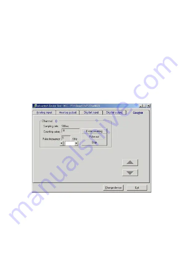
Click the
Counter
Tab to bring its test panel forth. The counter
channel
(Channel 0
) offers two options: Event counting
and Pulse out.
If you select Event counting, you need to first connect your clock
source to pin CNT0_CLK. The counter will start counting after the pin
CNT0_GATE is triggered. If you select Pulse Out, the clock source
will be output to pin CNT0_OUT. You can configure the
Pulse
Frequency
with the scroll bar.
Fig. 2-12: Counter tab on the Device Test dialog box
Only after your card device is properly set up, configured and tested,
can the device installation procedure be counted as complete. After the
device installation procedure is completed, you can safely proceed to
the next chapte
r, Signal Connection
s.
Summary of Contents for MIC-3716
Page 2: ...ii This page is left blank for hard printing...
Page 6: ...vi This page is left blank for hard printing...
Page 8: ...viii Table E 2 D A binary code table 117...
Page 11: ...1 Introduction 1 CHAPTER...
Page 17: ...7 Fig 1 1 Installation Flow Chart...
Page 21: ...11 Installation and Configuration CHAPTER 2...
Page 40: ...30 This page is left blank for hard printing...
Page 41: ...31 Signal Connections CHAPTER 3...
Page 44: ...34 Fig 3 1 I O connector pin assignments for the MIC 3716...
Page 50: ...40...
Page 54: ...44 This page is left blank for hard printing...
Page 55: ...45 Software Programming Overview CHAPTER 4...
Page 60: ...50 This page is left blank for hard printing...
Page 61: ...51 Calibration CHAPTER 5...
Page 77: ...67 Appendixes...
Page 81: ...71 Appendix B Block Diagrams...
Page 82: ...72 This page is left blank for hard printing...
Page 120: ...110 This page is left blank for hard printing...


