


35
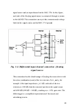
I/O Connector Signal Description
Table 3-1: I/O Connector Signal Description
Signal Name
Reference Direction
Description
AI<0… 15>
AIGND
Input
Analog Input Channels 0 through 15.
Each channel pair,
AI<i, i+1> (i = 0, 2, 4...14), can be configured as either two
single-ended inputs or one differential input.
AIGND
-
-
Analog Input Ground.
The three ground references
(AIGND, AOGND, and DGND) are connected together.
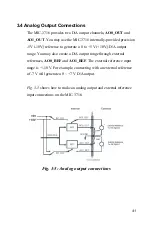
AO0_REF
AO1_REF
AOGND
Input
Analog Output Channel 0/1 External Reference.
AO0_OUT
AO1_OUT
AOGND
Output
Analog Output Channels 0/1.
AOGND
-
-
Analog Output Ground.
The analog output voltages are
referenced to these nodes. The three ground references
(AIGND, AOGND, and DGND) are connected together.
DI<0..15>
DGND
Input
Digital Input channels.
DO<0..15>
DGND
Output
Digital Output channels.
DGND
-
-
Digital Ground.
This pin supplies the reference for the
digital
channels
at the I/O connector as well as the +5VDC
supply. The three ground references (AIGND, AOGND, and
DGND) are connected together.
CNT0_CLK
DGND
Input
Counter 0 Clock Input.
The clock input of counter 0 can be
either external (up to 10 MHz) or internal (1 MHz), as set by
the software.
CNT0_OUT
DGND
Output
Counter 0 Output.
CNT0_GATE
DGND
Input
Counter 0 Gate Control.
PACER_OUT
DGND
Output
Pacer Clock Output.
This pin pulses once for each pacer
clock when turned on. If A/D conversion is in the pacer
trigger mode, you can use this signal as a synchronous
signal for other applications. A low- to- high edge triggers
the A/D conversion to start.
TRG_GATE
DGND
Input
A/D External Trigger Gate.
When TRG _GATE is
connected to +5 V, it will enable the external trigger signal
to input. When TRG _GATE is connected to DGND, it will
disable the external trigger signal to input.
EXT_TRG
DGND
Input
A/D External Trigger.
This pin is an external trigger signal
input for the A/D conversion. A low-to-high edge triggers A/D
conversion to start.
+12V
DGND
Output
+12 VDC Source.
+5V
DGND
Output
+5 VDC Source.
Summary of Contents for MIC-3716
Page 2: ...ii This page is left blank for hard printing...
Page 6: ...vi This page is left blank for hard printing...
Page 8: ...viii Table E 2 D A binary code table 117...
Page 11: ...1 Introduction 1 CHAPTER...
Page 17: ...7 Fig 1 1 Installation Flow Chart...
Page 21: ...11 Installation and Configuration CHAPTER 2...
Page 40: ...30 This page is left blank for hard printing...
Page 41: ...31 Signal Connections CHAPTER 3...
Page 44: ...34 Fig 3 1 I O connector pin assignments for the MIC 3716...
Page 50: ...40...
Page 54: ...44 This page is left blank for hard printing...
Page 55: ...45 Software Programming Overview CHAPTER 4...
Page 60: ...50 This page is left blank for hard printing...
Page 61: ...51 Calibration CHAPTER 5...
Page 77: ...67 Appendixes...
Page 81: ...71 Appendix B Block Diagrams...
Page 82: ...72 This page is left blank for hard printing...
Page 120: ...110 This page is left blank for hard printing...


