background image

EKI-1528-DR Series User Manual

46

7.

Locate the radio button correlating to the target port to modify and click on it to 
select it.

Verify the Device Port (EKI device physical serial port) and System Port (virtual COM
port for PC) settings before continuing. 

8.

Click 

Finish

 to complete the process. A Wizard complete! screen displays indi-

cating the completion of a successful procedure.

5.2.4

Confirming Virtual COM Settings

1.

On your desktop, navigate to 

Start > All Programs

 > 

EKI Device Configura-

tion Utility

 and click 

Advantech EKI Device Configuration Utility

to open the 

utility.

2.

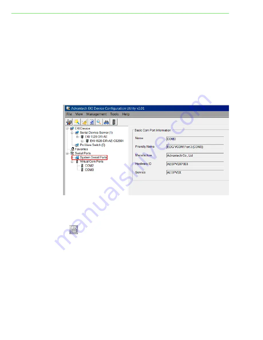
Locate 

Serial Ports

 menu in the menu pane and click on the Expand icon next 

to Virtual COM Ports to view a list of the mapped ports.

3.

Select a VCOM port to view its settings.

Figure 5.9 Serial Port Listing on EKI Device

For the next step, you will need to open the device manager on your system. Using
the Device Manager, you can both view and change the COM port settings. 

4.

On your desktop, click on the 

Start button

 and then on 

Control Panel

. A win-

dow displays showing all the available control panels.

5.

Click on 

Hardware and Sound

 (

Hardware

). A list of all available hardware con-

figuration options displays. 

6.

Under 

Devices and Printers

, click on the 

Device Manager

 link. A new window 

displays showing a list of all the available devices on your computer.

7.

Locate 

Ports

 (COM & LPT) and click on the expand icon. A list of all available 

serial and parallel port devices display. 

Note!

The following instructions are written for Windows 7; the Windows XP 
equivalent is displayed in parentheses (). The instructions may vary on 
other operating systems.

Summary of Contents for EKI-1528CI

Page 1: ...User Manual EKI 1528 DR Series Serial Device Server...

Page 2: ...llation Advantech assumes no liability under the terms of this warranty as a consequence of such events Because of Advantech s high quality control standards and rigorous testing most of our customers...

Page 3: ...able protection against harmful interference when the equipment is operated in a commercial environment This equipment generates uses and can radiate radio frequency energy and if not installed and us...

Page 4: ...ediately 1 x Serial Device Server 1 x Wall mounting Brackets 1 x DIN Rail Mounting Bracket and Screws 1 x CD ROM Warning Warnings indicate conditions which if not observed can cause personal injury Ca...

Page 5: ...the power source to avoid damage by transient overvoltage 12 Never pour any liquid into an opening This may cause fire or electrical shock 13 Never open the equipment For safety reasons the equipment...

Page 6: ...om damage To avoid electrical shock always disconnect the power from your PC chassis before you work on it Don t touch any components on the CPU card or other cards while the PC is on Disconnect power...

Page 7: ...in Assignment 12 2 2 3 Power Connection 13 Figure 2 12 P Fail Alarm Application Wiring 13 2 3 Installing the Configuration Utility 14 Figure 2 13 InstallShield Wizard 1 of 4 14 Figure 2 14 InstallShie...

Page 8: ...4 3 1 USDG TCP Client Mode 36 Figure 4 3 USDG TCP Client Mode 36 Figure 4 4 Peer for Receiving Data 37 4 3 2 USDG Data TCP Server Mode 37 Figure 4 5 USDG TCP Server Mode 37 Figure 4 6 USDG Data Mode 3...

Page 9: ...onfiguration Basic 55 6 5 2 Operation 55 Figure 6 5 Port Configuration Operation 56 6 5 3 Advanced 57 Figure 6 6 Port Configuration Advanced 58 6 6 Monitor 59 6 6 1 Setting 59 Figure 6 7 Monitor Setti...

Page 10: ...tion70 7 1 Overview 71 7 2 Telnet Console 71 Figure 7 1 Creating a Telnet Connection 71 Figure 7 2 Creating a Telnet Connection 71 Figure 7 3 Telnet Connection Console 72 7 3 Command List 72 Chapter A...

Page 11: ...Chapter 1 1Overview...

Page 12: ...ided in a later chap ter 1 2 Device Features Provides 2 x 10 100 Mbps Ethernet ports for LAN redundancy Provides COM port redirection Virtual COM TCP and UDP operation modes Supports up to 921 6 kbps...

Page 13: ...ace Mark Flow Control XON XOFF RTS CTS DTR DSR Baud Rate 50 bps 921 6 kbps any baud rate setting Protection Built in 15 KV ESD for all signals Power Power Consumption EKI 1528I 5W EKI 1528CI 6W Power...

Page 14: ...Chapter 2 2Getting started...

Page 15: ...rs on page 7 for further details 2 Default button Press at least 10secs to reset device to default settings 3 ETH port RJ45 ports x 2 See LED Indicators on page 7 for further details 4 Serial port DB9...

Page 16: ...Screw holes x6 used in the installation of a wall mounting plate 2 DIN Rail mounting plate Mounting plate used for the installation to a standard DIN rail 1 1 2 No Item Description 1 Terminal block C...

Page 17: ...The device server has been located by utility s location function Off System is not working 4 Ethernet Amber Blinking Ethernet port is transmitting or receiv ing data Steady on Ethernet has a good lin...

Page 18: ...1 1 DIN Rail Mounting The DIN rail mount option is the quickest installation option Additionally it optimizes the use of rail space The metal DIN rail kit is secured to the rear of the serial device...

Page 19: ...the bottom of the server towards the DIN rail until it snaps into place Figure 2 6 Installing the DIN Rail Mounting Kit Removing the DIN Rail Mounting Kit 1 Push the server down to free the bottom of...

Page 20: ...will need to remove the DIN rail plate 1 Rotate the device to the rear side and locate the DIN mounting plate 2 Remove the screws securing the DIN mounting plate to the rear panel of the server 3 Rem...

Page 21: ...mount plates as a guide to mark the locations of the screw holes 8 Drill four holes over the four marked locations on the wall keeping in mind that the holes must accommodate wall sinks in addition t...

Page 22: ...gure Figure 2 10 Wall Mount Installation 13 Once the device is installed on the wall tighten the screws to secure the device 2 2 2 Serial Connection EKI 1528 Series provides eight ports DB9 male conne...

Page 23: ...ay opens if power input 1 or 2 fails In a wiring example where an LED is connected to the relay output the LED would be off in an Open state Warning Power down and disconnect the power cord before ser...

Page 24: ...pro gram the path for the setup program on the CD ROM is as follows E EKI_Device_Configuration_Utility_v2 01 exe 3 If there is an existing COM port mapping utility on the host PC remove it at this ti...

Page 25: ...ess I Agree to continue or Cancel to stop the installation Figure 2 14 InstallShield Wizard 2 of 4 The InstallShield continues and a status screen displays The default installation path is C Program F...

Page 26: ...er Manual 16 6 Once the installation of the package is finished a Configuration Utility Setup screen displays Click Finish to conclude the process and exit the InstallShield Wizard Figure 2 16 Install...

Page 27: ...Chapter 3 3Utility Configuration...

Page 28: ...te Advantech serial device servers easily The utility provides access to the following functions Configure the network settings you can set the IP address Gateway address and Subnet mask View and set...

Page 29: ...igura tion page displays Note The configuration utility makes use of TCP UDP ports 5048 and 5058 to communicate with the Advantech EKI serial device server T Please reserve TCP UDP port 5048 and 5058...

Page 30: ...serial device server to the network Icon Item Description Item Description Main Window Settings Maximum Main Window On Load Check the box to enable the limiting of main windows on load to the maximum...

Page 31: ...ond Enter a value to specify the time to auto detection time 1 means disable auto detection Auto detect devices every X second Enter a value to specify the time to auto detect devices Check device ali...

Page 32: ...n the device name to show the features of the specific device Click on the before the model name and the utility will expand the tree structure to show the individual device name Click on the before t...

Page 33: ...rmation In the serial port information frame it dis plays the operation mode status and connected host IP Figure 3 6 Selecting a Group Click on the before the device name and the utility will expand t...

Page 34: ...AutoIP mode to automatically assign IP addresses through a DHCP server BOOTP AutoIP mode to automatically assign an IP address through the con figuration server DHCP BOOTP AutoIP mode to automatically...

Page 35: ...and DNS BOOTP Auto IP BOOTP Server assigned IP address DHCP BOOTP Auto IP DHCP Server assigned IP address Subnet Mask Default Gate way and DNS or BOOTP Server assigned IP address If the DHCP Server d...

Page 36: ...ate the Serial Device Server When several serial device servers are connected to the network identification of a specific serial device is possible through the Locate function To locate the serial dev...

Page 37: ...Lock Unlock the Serial Device Server Password Protection The configuration utility provides the Lock Device function to make it more secure You need to set up a password the first time by clicking Loc...

Page 38: ...e Figure 3 12 Lock the Serial Device Server 3 Enter a password and re confirm the profile password Figure 3 13 Enter a Password 4 After re confirming the password the serial device server will reboot...

Page 39: ...ank The serial device server will restart and store the new password in the memory Figure 3 14 Unlock the Serial Device Server 3 4 3 Change Password To unlock the serial device server 1 Right click a...

Page 40: ...vice allows you to reset the serial device server The function discon nects both the ethernet and serial connections The function also allows the serial device server to save new configuration setting...

Page 41: ...irmware Advantech continually upgrades its firmware to keep up with the ever expending world of computing You can use the update firmware function in the utility to carry out the upgrade procedure Ple...

Page 42: ...e completely click on the OK button The serial device server will restart automat ically Note Be sure that the host PC Ethernet network domain is as same as the EKI 1528 Series serial device server or...

Page 43: ...Chapter 4 4Selecting an Operating Mode...

Page 44: ...erver You can configure the serial device server and enable the Virtual COM port using one integrated utility Advantech EKI Device Configuration Utility allows you to configure Microsoft applications...

Page 45: ...ta will also be transmitted to the connected hosts simultaneously 4 2 2 Round Robin mode By enabling the Response Timeout parameter the EKI 1528 Series operates in Round Robin mode Each serial port su...

Page 46: ...EKI 152X series to one host or several hosts You can configure the IP address and TCP port number of the network hosts connected to the EKI serial device server using the Advantech Serial Device Serv...

Page 47: ...device server This operation mode supports a maximum of five simultaneous con nections for each serial port on an EKI serial device server from a single or multiple hosts However a multi host connect...

Page 48: ...e is 1024 65533 If an unknown caller wants to connect to the system and request services they must define the TCP UDP port to carry a long term conversation Each node on a TCP IP network has an IP add...

Page 49: ...Mode is designed for use with legacy operating systems such as MSDOS that do not support TCP IP Ethernet By connecting one of the EKI s serial ports to the MS DOS computer s serial port it is possibl...

Page 50: ...ies devices to a local COM port on a host computer RFC2217 defines general COM port control options based on the Telnet protocol Third party drivers supporting RFC2217 are widely available on the Inte...

Page 51: ...Chapter 5 5Setting Up COM Port Redirector...

Page 52: ...al COM port management utility are integrated into one utility with same GUI The Advantech EKI Device Configuration Utility can create all Virtual COM ports using the Auto Mapping function or by using...

Page 53: ...Selected Ports Once the mapping function is initialized a successful mapping process results in the virtual mapping of the designated physical serial port and VCOM PC port See the following figure Fi...

Page 54: ...his is the physical serial port on the EKI device 6 In the Host COM Port drop down menu select the target COM port to map This is the virtual port on the target PC Figure 5 6 Selecting Manual Mapping...

Page 55: ...y and click Advantech EKI Device Configuration Utilityto open the utility 2 Under Serial Device Servers locate your server and click the icon to expand the listing 3 From the tool bar select Configura...

Page 56: ...rts 3 Select a VCOM port to view its settings Figure 5 9 Serial Port Listing on EKI Device For the next step you will need to open the device manager on your system Using the Device Manager you can bo...

Page 57: ...ration The newly mapped VCOM port is listed under the same mapped settings used in the previous steps The settings correspond to the VCOM port configuration on the EKI device see the following figure...

Page 58: ...Device Configuration Utility A Remove Port confirmation window displays 5 Click OK to continue with the removal process or Cancel to return to the previ ous menu Once the procedure is completed a prom...

Page 59: ...option is selected an external test will be run to check that the con nection signals for each port are working properly For the test you will need to con nect each port to a loopback tester provided...

Page 60: ...EKI 1528 DR Series User Manual 50 1 Click Simple Serial Test in the Tools menu Figure 5 14 Running a Diagnostic Test...

Page 61: ...Chapter 6 6Web Configuration...

Page 62: ...or this device Once the IP is entered you will be presented with the following windows 6 2 Accessing the Web Page 6 2 1 Accessing the Web Page via Configuration Utility To access the web page via conf...

Page 63: ...re Item Description Firmware version Displays the current firmware version of the device Revision number Displays the revision number of the device Device Name Enter the device name up to 31 alphanume...

Page 64: ...Setting mode Static IP DHCP or BOOTP MAC Address Enter the MAC address to which packets are statically forwarded IP Address Enter a value to specify the IP address of the interface The default is 10 0...

Page 65: ...lated attri butes for port configuration Note All new configurations will take effect after rebooting To reboot the device click Tools Reboot Item Description Type Click the drop down menu to select a...

Page 66: ...timeout period Response Timeout ms Enter a value to define the response timeout period Frame Break ms Enter a value to specify the frame break time Pack conditions Pack sent immediately when reach 10...

Page 67: ...nt pack immediately by interval By end character Click the option to sent pack immediately by end character By character time out Click the option to sent pack immediately by character timeout Peer fo...

Page 68: ...Timeout Detection Click the option to disable the serial port character timeout detection Disable Multiple Connection Click the option to disable the multi access function Then only one TCP connection...

Page 69: ...page click Monitor Setting Figure 6 7 Monitor Setting TTL Transmitter Trigger Level Click the option to designate to suspend or resume transmission FCL Flow Control Lower Trigger Levels Click to set r...

Page 70: ...CTS Display the current RTS CTS status of the selected port XON XOFF Display the current XON OFF status of the selected port DTR DSR Display the current DTR DSR status of the selected port Save Click...

Page 71: ...t On the Alert Settings page you may configure how administrators are notified by ce tain system network configuration power and cellular connection events Rely on the events administrators can collec...

Page 72: ...mail warnings will be sent Email addresses 1 4 This is the e mail address or addresses to which the automatic e mail warnings will be sent SNMP Trap Server Trap Server Use this field to indicate the...

Page 73: ...record or send event mesages System event notification is available for cold start warm start authentication failure IP address Password change serial DCD DSR port change and Ethernet link down inform...

Page 74: ...click Alarm Event Figure 6 11 Alarm Event 1 of 2 The following table describes the items in the previous figure Item Description System Event Cold Start Click the option to select a warning type when...

Page 75: ...assword is entered IP address changed Click the option to select a warning type when the IP address is changed Password changed Click the option to select a warning type when the password is changed E...

Page 76: ...gd Syslogd Message Figure 6 13 Syslogd Syslogd Message 6 9 Tools The EKI serial device server provides tools for access to ping and reset functions 6 9 1 Ping The ping page can help users diagnose eth...

Page 77: ...e last time you issued a save will be lost Item Description IP Enter the IP address or host name of the station to ping The initial value is blank The IP Address or host name you enter is not retained...

Page 78: ...ange Password The Change Password function allows you to easily update your current password from a single menu To access this page click Management Change Password Figure 6 16 Management Change Passw...

Page 79: ...than 0 restricted to listed Access IP listing To access this page click Management Secure access IP Figure 6 17 Management Secure access IP The following table describes the items in the previous fig...

Page 80: ...Chapter 7 7Telnet Serial Console Configuration...

Page 81: ...d other related terminal software 7 2 Telnet Console Create a new connection You can create a new Telnet connection and assign a connection name for the con sole configuration Figure 7 1 Creating a Te...

Page 82: ...ports information portadv Show or configure the serial ports advanced settings mvcom Show or configure the serial ports in Virtual COM mode mctr Show or configure the serial ports in Control mode USDG...

Page 83: ...en Parity parity o Odd Parity parity m Mark Parity parity s Space Parity Set serial baud rate parity and numbers of data bits numbers of stop bits Usage port nn all mode vcom ctrl data Set serial port...

Page 84: ...bytes or time ms and character HEX value 0 None Setting mctrl Usage mctrl Show port mode and mode informations Usage mctrl nn all Set port nn all as control mode Usage mctrl nn all idleto tcpp atp gua...

Page 85: ...ew password Usage password old new 1 31 characters Confirm the old password and set new password alarm Usage alarm Show current alarm informations Usage alarm mail server null address from null addres...

Page 86: ...t enable disable Enable Disable telnet function Usage service snmp enable disable Enable Disable SNMP function mrfc2217 Usage mrfc2217 Show all port mode and mode informations Usage mrfc2217 nn all Se...

Page 87: ...Appendix A ATCP and UDP Port Numbers...

Page 88: ...ation Utility 5202 TCP VCOM RVCOM 9999 TCP Firmware Download 22 TCP SSH 23 TCP Telnet 25 TCP SMTP Mail Client 53 TCP UDP DNS 67 UDP BOOTP Server DHCP 68 UDP BOOTP Client DHCP 80 TCP Web Interface HTTP...

Page 89: ...tions are subject to change without notice No part of this publication may be reproduced in any form or by any means electronic photocopying recording or otherwise without prior written permis sion of...

Reviews: