Wolf Series RS-485 Remote I/O Module
Wolf series Remote IO Module User's Manual 121
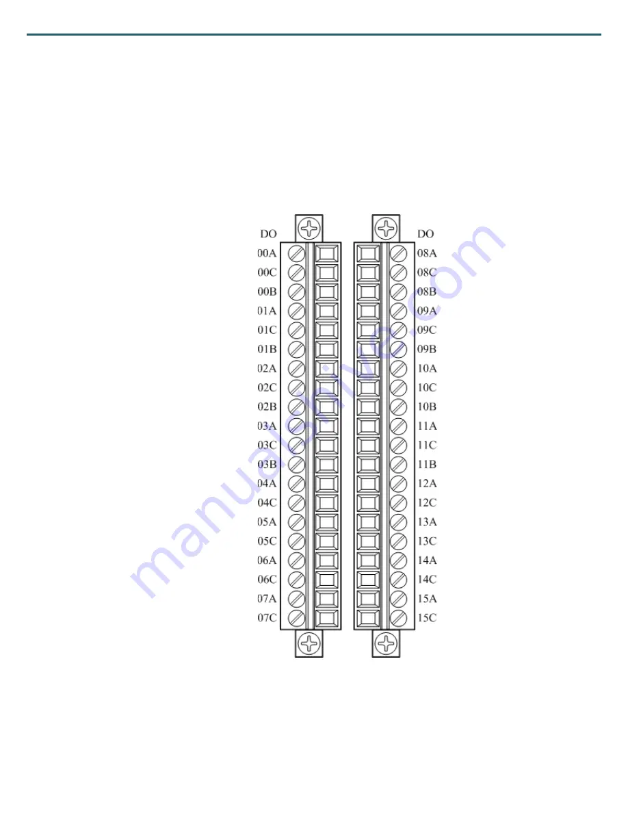
4.6 W-M1B404 16-Channel Relay Output
Module
4.6.1 Terminal Assignment
Page 1: ...Wolf series Remote IO Modules User s Manual ...
Page 2: ... otherwise Advanio guarantee the safety and stability of all the applications The series modules which have been tested under rigorous process conform to the criteria declared There is little chance that customers will need any further after services Nevertheless within the period of the warranty the defective product will be repaired or be replaced at no extra cost while for out of warranty servi...
Page 3: ...confirmation within 3 days while we process your request referring to the information stated on this RMA Request Form Red color sections will be filled by our sales representative Thank you for your cooperation Request Date RMA No Company Name Contact person Phone Fax Return Address Other information Return Shipping Date Item Model No S N No Reason of Return Received Qty 1 2 3 4 5 6 7 8 9 ...
Page 4: ... EMS are designed for module protection Hence we strongly recommend pairing Wolf series modules with industrial chassis certified by CE Certification This device complies with Part 15 of the FCC Rules Operation is subject to the following two conditions 1 this device may not cause harmful interference and 2 this device must accept any interference received including interference that may cause und...
Page 5: ...ply 15 2 1 5 Connecting Communication Interface 17 2 1 6 IO Connection 18 2 1 7 Indicators 20 2 1 8 Channel Label 21 2 1 9 Setup Utility 22 2 1 10 Communication Setup 22 2 1 11 Factory Reset 24 2 1 12 Isolated Type RS 232 RS 485 Converter Optional 25 2 1 13 Repeater Optional 25 2 2 Example Single Module 25 2 3 Example Multiple Modules 26 2 4 System Configuration 27 2 4 1 Daisy Chain 27 2 4 2 Star ...
Page 6: ...Module 51 3 5 1 Terminal Assignment 51 3 5 2 Block Diagram 52 3 5 3 Channel Connecting 53 3 5 4 IO Specifications 54 3 5 5 Related Reference 54 3 5 6 MODBUS Address 57 3 6 W M1B109 110 8 16 channel Current Input Module 62 3 6 1 Terminal Assignment 62 3 6 2 Block Diagram 63 3 6 3 Channel Connecting 64 3 6 4 IO Specifications 65 3 6 5 Related Reference 65 3 6 6 MODBUS Address 67 3 7 W M1B111 112 8 1...
Page 7: ... Channel Connecting 98 4 2 4 IO Specifications 99 4 2 5 Related Reference 99 4 2 6 MODBUS Address 102 4 3 W M1B401 16 Channel Digital Output Module 104 4 3 1 Terminal Assignment 104 4 3 2 Block Diagram 105 4 3 3 Channel Connecting 105 4 3 4 IO Specifications 106 4 3 5 Related Reference 106 4 3 6 MODBUS Address 107 4 4 W M1B402 32 Channel Digital Output Module 109 4 4 1 Terminal Assignment 109 4 4 ...
Page 8: ...nel Digital Input 16 Channel Digital Output Module 127 4 7 1 Terminal Assignment 127 4 7 2 Block Diagram 128 4 7 3 Channel Connecting 129 4 7 4 IO Specifications 130 4 7 5 Related Reference 130 4 7 6 MODBUS Address 134 4 8 W M1B502 16 Channel Digital Input 8 Channel Relay Output Module 137 4 8 1 Terminal Assignment 137 4 8 2 Block Diagram 138 4 8 3 Channel Connecting 139 4 8 4 IO Specifications 13...
Page 9: ...of input output channels for user s choice for instance 8 16 and 32 Wolf series module is a kind of remote I O Module which is host sends command to control it After receiving commands sent by host remote control modules start responding The protocol used in between host and modules is Modbus RTU Furthermore to have a more efficient application a great variety of baud rates for user s selection 12...
Page 10: ... 2km 1 3 Set Up and Use The rotary switch provided by Wolf series module is a handy gadget for user to facilitate the address setup during the installation Utility software is employed to set up the module configuration parameter The factory default can be reset by pressing INIT for at least 3 second Furthermore EEPROM built in the modules is detachable and can be changed on new module to retain t...
Page 11: ...dule will reset all outputs to SAFE mode to prevent any improper operations on the controlled target Watchdog of Modbus functions as following table Address Function R W Initial value 44108 0x100B Timeout value 0 1s Range 0 0x00FF R W 0x0000 44109 0x100C Function enable disable 0x0001 Enable 0x0000 Disable R W 0x0000 44110 0x100D Watchdog status 0x0001 Timeout 0x0000 Normal R W 0x0000 Module watch...
Page 12: ...eries RS 485 Remote I O Module Wolf series Remote IO Module User s Manual 4 1 5 Power Requirements DC ranged from 10V to 60V is applicable to Wolf Series Module the reverse power protection is also available ...
Page 13: ...Module Wolf series Remote IO Module User s Manual 5 1 6 RS 485 Network Connections The most commonly used communication interface is adapted co called RS 485 It provides a remote transmitting and is applicable to all remote connect ...
Page 14: ...485 Remote I O Module Wolf series Remote IO Module User s Manual 6 1 7 Environmental Safety Wolf series modules are EMC certified in many countries With EMI and EMS FREE to ensure the environmental quality of modules ...
Page 15: ...Wolf Series RS 485 Remote I O Module Wolf series Remote IO Module User s Manual 7 1 8 Dimension Wolf series module dimension as following Unit mm ...
Page 16: ...S 232 to RS 485 converter from our company is necessary if this PC workstation is equipped RS 232 port only Also a USB to RS 485 converter of our company is alternative solution These isolated converters are based on photo couple to protect your PC workstation 2 1 2 Wolf Module Ports connection and setup of Wolf Series module is shown as figures below The external connecting and construction will ...
Page 17: ...ecting power and RS 485 via this fixed seat It support attach detach module rapidly and easy extendable IO connector Wiring IO signals for your application RS 485 port Major communication port Power input power For power input System indicator Represent system status Detachable DIN RAIL fixed seat Separated IO connector ModBus node address switch ...
Page 18: ... to factory default 2 1 3 Installation DIN rail mounting Mounting the detachable DIN rail on standard DIN35 rail therefore more modules can be extended if required DIN rail module chain installation Fixed seats been installed on DIN35 rail also using connecting pin array to connect each fixed seats one by one as shown as following figure The communication and power would be chain connected Chain c...
Page 19: ...mote I O Module Wolf series Remote IO Module User s Manual 11 Step 2 Push modules together on DIN rail and connected by pin array A chained fixed seat of module on DIN rail as shown as following figure Connecting pin array ...
Page 20: ...O Module Wolf series Remote IO Module User s Manual 12 Step 3 Insert each I O modules to detachable fixed seats by vertical direction Step 4 A complete module chain on DIN rail as show as following figure 模塊串接塑膠 固定片 Plastic Buckle ...
Page 21: ...cations of screw hole as shown as following figure Insert each modules to fixed seats on wall as shown as following figure Module grounding If Wolf series modules were installed on an aluminum DIN rail then the module grounding would utilize aluminum rail for F G Frame Ground the grounding also could be connected by connector as shown as following figure Module grounding by power connector Screwin...
Page 22: ...m DIN rail A metal grounding tab could be installed between modules and rail The install location of metal grounding tab as shown as following figure We strongly recommends a suitable Grounding Frame Grounding is necessary to ensure the system stability If the grounding of power supply is poor or there have noise on frame grounding then it need isolate frame grounding of module Use a plastic groun...
Page 23: ...it industrial application there is power regulator inside for system power stabilization to supply high quality power if supplied power is within support rang It is ideally on voltage and current in module are inversely proportional but the power ripple must be limited to 5V Vpp How wire power connector as shown as following figure VS GND F G Power Supply 10V to 60VDC Plastic grounding tab ...
Page 24: ...ower would be parallel connected on DIN rail so the power connector are on same situation While connecting the power supply to one of them on the rail then the power would distribute to every module via rail Be careful only one power source could be connecting to one set of modules on one rail The maximum number of modules on one rail is 10 modules and power consumption approximant 30W Using power...
Page 25: ... is show the RS 485 connection When DIN rail mounting with modules alongside and the mounting base are connected to the dock connector RS485 Signals can enter from the first module only and out from the last module only It is prohibited to use the intermediate module for the pick out to avoid communication instability If the base is not connected to the dock connector then every module need to be ...
Page 26: ...User can choose the suitable I O feature on module to fit specified application Please refer to the section of module information and check if each I O channel has been assigned appropriately The description of each I O channels on the back side of cover It is for user quick reference easily IO connector ...
Page 27: ...ng I O terminal Restore terminal to module 1 Insert the flathead screwdriver into the position as shown as above 2 Push down the screwdriver 3 Remove the terminal by pulling the hook of up side 4 Terminal removed 1 Put the terminal on module 2 Push the top side and bottom side by two hands then complete ...
Page 28: ...mmunication Lighting Polling timeout Flashing every 0 5 sec Normal Lighting Abnormal A flash pattern as Lighting 2 sec Off 1 sec Lighting 0 5 sec Off 1sec EEPROM module accessing fail Flash pattern as Lighting 2 sec Off 1 sec Lighting 0 5 sec 2 times Off 1 sec EEPROM accessing failed If it is new part or not be initialized please perform EEPROM initial procedures as appendix section 1 Flashing pat...
Page 29: ...button on up side of connector board 3 sec then module would perform init procedure and store new parameter into EEPROM Keeping the parameters which are in EEPROM same as system 2 1 8 Channel Label Tabs under the plastic film are accessible for user to record the assignment of each channel If you want to change the tabs please download Excel file via Advanio official website print it and cut out t...
Page 30: ...hrough RS 485 converter USB to RS 485 converter Utility and setup guideline could be obtained from Advanio website 2 1 10 Communication Setup To setup Wolf series module MODBUS node address should be determined first The factory default to the node address of Wolf M1B series module is 01 The node address could be setup by two hexadecimal coded rotary switches The range of node address is from 0x01...
Page 31: ...me format and baud rate could be changed via utility or MODBUS command The baud rate range is from 1200bps to 115 2Kbps Even and Odd parity check The setup utility could be downloaded via Advanio official website set up MODBUS command of RS 485 as the following Address Function R W Initial value 44107 0x100A Com port parameter 2 bytes High Byte Low Byte 0x00 8 N 1 0x01 8 N 2 0x02 8 E 1 0x03 8 O 1 ...
Page 32: ...Push Button to complete INIT Push Button functions are described as follows Push INIT and hold for 3 seconds the LED indication of power communication and system will flash 3 times at 0 5 second interval After initial operation Resume factory default and reset modules Baud rate 9600bps Data format N 8 1 Refer to chapter 4 for factory default setting Push Button ...
Page 33: ...e address for the converter is not required 2 1 13 Repeater Optional With a communication distance surpasses 4000 feet 1200m or more than 32 modules are used expanding repeaters may be needed Maximum number of modules is 247 by 8 repeaters 2 2 Example Single Module Construction of basic modules featuring network connecting of Wolf series module single is show as figures below D D D D VS GND F G Ho...
Page 34: ... IO Module User s Manual 26 2 3 Example Multiple Modules Construction of multiple modules featuring network connecting of Wolf series modules is show as figures below D D D D VS GND F G Host RS 485 Power Supply 10 60VDC D D D D VS GND F G Local Power Supply ...
Page 35: ...protocol When communicating via host or terminal is required RS485 would be taken in consideration in term of different system architecture Star topology daisy chain and random topology will be briefed in the next sections 2 4 1 Daisy Chain In each segment the last node to connect modules must be repeater with another end connected to the main cable it served as an important medium Each repeater c...
Page 36: ...s Manual 28 2 4 2 Star Topology All the repeaters are connected to the main network through a cable and the modules are connected to the repeaters It forms a tree 2 4 3 Random Topology A combination of star and daisy chain topologies can be designated for every requirement ...
Page 37: ...tion module and store the EEPROM module on new module set the MODBUS node address same as malfunction module by rotary switch Done If terminal and connectors been restore correctly The malffunction would be caused by EEPROM Then use the EEPROM along with new module and configure the appropriate setting by software Yes No EEPROM Replacement EEPROM location is marked in the following figure Wolf Ser...
Page 38: ...eries Remote IO Module User s Manual 30 Procedures of remove EEPROM To remove EEPROM follow the steps below Procedures of restore EEPROM To restore EEPROM follow the steps below 更換 IO 標示牌步驟 PUSH PUSH PUSH 抽出壓克力板 進行更換標示 牌 再將壓克 力板裝入即可 安裝模組川接塑膠扣步驟 ...
Page 39: ...Wolf Series RS 485 Remote I O Module Wolf series Remote IO Module User s Manual 31 Chapter 3 Analog Module Information 3 1 W M1B101 Coming Soon ...
Page 40: ...Wolf Series RS 485 Remote I O Module Wolf series Remote IO Module User s Manual 32 3 2 W M1B102 Coming Soon ...
Page 41: ...ries RS 485 Remote I O Module Wolf series Remote IO Module User s Manual 33 3 3 W M1B103 104 8 16 Channel Universal Analog Input Module with High Voltage Protection 3 3 1 Terminal Assignment W M1B103 W M1B104 ...
Page 42: ...mote IO Module User s Manual 34 3 3 2 Block Diagram Power Regulator VS GND 5V GND V V RS485 Interface D D Embedded Controller Photo isolation 2CH ADC Front End Circuit 120Ω 00 00 Front End Circuit 120Ω 01 01 2CH ADC Front End Circuit 120Ω 07 07 W M1B103 ...
Page 43: ...ND 5V GND V V RS485 Interface D D Embedded Controller Photo isolation 2CH ADC Front End Circuit 120Ω 00 00 Front End Circuit 120Ω 01 01 2CH ADC Front End Circuit 120Ω 07 07 W M1B104 Embedded Controller 2CH ADC Front End Circuit 120Ω 08 08 Front End Circuit 120Ω 09 09 2CH ADC Front End Circuit 120Ω 15 15 ...
Page 44: ...0 1V 0 5V 0 10V Current Input 20mA 4 20mA 0 20mA Slide switch select Direct Sensor Input J K T E R S B N Burn out Detection Yes all V 4 20 mA all T C Channel Independent Configuration Yes Sampling Rates 2 5 samples second per channel Resolution 16 bit Accuracy 0 1 FSR Input Impedance Voltage 2MΩ Current 120 Ω Span Drift 25 ppm Zero Drift 6 μV Input Voltage Protection 240V Common Mode Voltage 240V ...
Page 45: ...e 40705 40720 0x02C0 0x02CF CH0 CH15 Input signal type setup R W 0x0106 Caution If Current input is selected please turn the switch to Current Input by a flathead screwdriver While switching to voltage and thermocouple it is required to turn the switch to the appropriate mode See figure below Signals detect range Value Input range Initial value Voltage Input 0x0101 0 10 V 0x0102 0 5 V 0x0103 0 1 V...
Page 46: ...pe R Thermocouple 50 1768 C 0x0306 Type S Thermocouple 50 1768 C 0x0307 Type B Thermocouple 0 1820 C 0x0308 Type N Thermocouple 270 1300 C 3 3 5 2 CJC Cold Junction Compensation There is thermal sensor built in the module the purpose is cold junction compensation to thermocouple Modbus command is shown below Address Function R W Initial value 00524 0x020B CJC Enable 0 disable 1 enable R W 0 40609 ...
Page 47: ...0 FFFF 65535 0x0106 10 V 8000 32768 7FFF 32767 0x0107 5 V 8000 32768 7FFF 32767 0x0108 1 V 8000 32768 7FFF 32767 0x0109 500 mV 8000 32768 7FFF 32767 0x010A 100 mV 8000 32768 7FFF 32767 Current Input 0x0201 4 20mA 0 0 FFFF 65535 0x0202 0 20 mA 0 0 FFFF 65535 0x0203 20 mA 8000 32768 7FFF 32767 Thermocouple Input 0x0301 Type J Thermocouple 210 1200 C E999 5735 7FFF 32767 0x0302 Type K Thermocouple 27...
Page 48: ...2000 0x0302 Type K Thermocouple 270 1372 C 2700 13720 0x0303 Type T Thermocouple 270 400 C 2700 4000 0x0304 Type E Thermocouple 270 1000 C 2700 10000 0x0305 Type R Thermocouple 50 1768 C 500 17680 0x0306 Type S Thermocouple 50 1768 C 500 17680 0x0307 Type B Thermocouple 0 1820 C 0 18200 0x0308 Type N Thermocouple 270 1300 C 270 13000 3 3 5 4 Signal Value Once completing the setup please enter the ...
Page 49: ...can fine tuning of temperature Setting address is show below Address Function R W Initial Value 40577 40592 0x0240 0x024F CH0 CH15 temp offset Unit 0 01 Range 50 00 50 00 R W 0x0000 3 3 6 MODBUS Address 3 3 6 1 W M1B103 Modbus Address Table Coil 0xxxx 1xxxx Address Function R W Initial Value 00524 0x020B CJC Enable 0 Disable 1 Enable R W 0 00537 0x0218 Allow calibration 0 Disallow 1 Allow R W 0 00...
Page 50: ...x02E0 AI Result format of measurement 0x0000 Hex 0x0001 Engineering R W 0x0000 40577 0x02F4 CH0 CH7 Calibrate maximum value to each channel Each bit map to corresponding channel Ex Bit 0 1 Calibrate CH0 Bit 1 1 Calibrate CH1 W 0x0000 40578 0x02F5 CH0 CH7 Calibrate 0 level to each channel Each bit map to corresponding channel W 0x0000 40579 0x02F6 CH0 CH7 Perform internal calibration to each channe...
Page 51: ...R W 0x0000 44109 0x100C System watch dog 0x0001 Enable 0x0000 Disable R W 0x0000 44110 0x100D Status of system watch dog 0x0001 Timeout 0x0000 Normal R W 44111 0x100E Counter of communication frame R 0x0000 3 3 6 2 W M1B104 Modbus Address Table Coil 0xxxx 1xxxx Address Function R W Initial Value 00524 0x020B CJC Enable 0 Disable 1 Enable R W 0 00537 0x0218 Allow calibration 0 Disallow 1 Allow R W ...
Page 52: ...01 Engineering R W 0x0000 40577 0x02F4 CH0 CH15 Calibrate maximum value to each channel Each bit map to corresponding channel Ex Bit 0 1 Calibrate CH0 Bit 1 1 Calibrate CH1 W 0x0000 40578 0x02F5 CH0 CH7 Calibrate 0 level to each channel Each bit map to corresponding channel W 0x0000 40579 0x02F6 CH0 CH7 Perform internal calibration to each channel Each bit map to corresponding channel W 0x0000 405...
Page 53: ... 1 0x03 8 O 1 0x03 1 2K 0x04 2 4K 0x05 4 8K 0x06 9 6K 0x07 19 2K 0x08 38 4K 0x09 57 6K 0x0A 115 2K R W 0x0006 44108 0x100B Watch dog timer unit 0 1s Range 0 0x00FF R W 0x0000 44109 0x100C System watch dog 0x0001 Enable 0x0000 Disable R W 0x0000 44110 0x100D Status of system watch dog 0x0001 Timeout 0x0000 Normal R W 44111 0x100E Counter of communication frame R 0x0000 ...
Page 54: ...Wolf Series RS 485 Remote I O Module Wolf series Remote IO Module User s Manual 46 3 4 W M1B105 106 8 16 Channel Universal Analog Input Module 3 4 1 Terminal Assignment W M1B105 W M1B106 ...
Page 55: ...mote IO Module User s Manual 47 3 4 2 Block Diagram Power Regulator VS GND 5V GND V V RS485 Interface D D Embedded Controller Photo isolation 2CH ADC Front End Circuit 120Ω 00 00 Front End Circuit 120Ω 01 01 2CH ADC Front End Circuit 120Ω 07 07 W M1B105 ...
Page 56: ...ND 5V GND V V RS485 Interface D D Embedded Controller Photo isolation 2CH ADC Front End Circuit 120Ω 00 00 Front End Circuit 120Ω 01 01 2CH ADC Front End Circuit 120Ω 07 07 W M1B106 Embedded Controller 2CH ADC Front End Circuit 120Ω 08 08 Front End Circuit 120Ω 09 09 2CH ADC Front End Circuit 120Ω 15 15 ...
Page 57: ...00mV 0 500mV 0 1V 0 5V 0 10V Current Input 20mA 4 20mA 0 20mA Slide switch select Direct Sensor Input J K T E R S B N Burn out Detection Yes all V 4 20 mA all T C Channel Independent Configuration Yes Sampling Rates 2 5 samples second per channel Resolution 16 bit Accuracy 0 1 FSR Input Impedance Voltage 2MΩ Current 120 Ω Span Drift 25 ppm Zero Drift 6 μV Input Voltage Protection 35V Power Consump...
Page 58: ...O Module Wolf series Remote IO Module User s Manual 50 3 4 5 Related Reference 3 4 6 MODBUS Address Function of W M1B105 is the same with W M1B103 funtcion of W M1B106 is the same with W M1B104 please refer to section 3 3 5 3 3 6 ...
Page 59: ...Wolf Series RS 485 Remote I O Module Wolf series Remote IO Module User s Manual 51 3 5 W M1B107 108 8 16 Channels Thermoucouple Input Module 3 5 1 Terminal Assignment W M1B107 W M1B108 ...
Page 60: ...ries Remote IO Module User s Manual 52 3 5 2 Block Diagram Power Regulator VS GND 5V GND V V RS485 Interface D D Embedded Controller Photo isolation 2CH ADC Front End Circuit 00 00 Front End Circuit 01 01 2CH ADC Front End Circuit 07 07 W M1B107 ...
Page 61: ...S GND 5V GND V V RS485 Interface D D Embedded Controller Photo isolation 2CH ADC Front End Circuit 00 00 Front End Circuit 01 01 2CH ADC Front End Circuit 07 07 W M1B108 Embedded Controller 2CH ADC Front End Circuit 00 00 Front End Circuit 01 01 2CH ADC Front End Circuit 07 07 3 5 3 Channel Connecting ...
Page 62: ... Yes Sampling Rates 2 5 samples second per channel Resolution 16 bit Accuracy 0 1 FSR Input Impedance 2MΩ Span Drift 25 ppm Zero Drift 6 μV Input Voltage Protection 35V Power Consumption 1 6W 24V 2 8W 24V 3 5 5 Related Reference 3 5 5 1 Input Signal Type Setup Input ranges type for each analog signal is adjustable Modbus command is shown below Address Function R W Initial value 40705 40712 0x02C0 ...
Page 63: ... Compensation There is thermal sensor built in the module the purpose is cold junction compensation to thermocouple Modbus command is shown below Address Function R W Initial value 00524 0x020B CJC Enable 0 disable 1 enable R W 0 40609 40624 0x0260 0x026F CH0 CH15 CJC Scale Unit 0 01 Range 50 00 50 00 R W 0x0000 40641 0x0280 CJC Value Unit 0 1 R 40642 0x0281 CH8 CH15 CJC Value 0 01 R 40657 0x0290 ...
Page 64: ...00 C E56A 6806 7FFF 32767 Engineering Unit data range Value Range Min value Max value Thermocouple Input 0x0301 Type J Thermocouple 210 1200 C 2100 12000 0x0302 Type K Thermocouple 270 1372 C 2700 13720 0x0303 Type T Thermocouple 270 400 C 2700 4000 0x0304 Type E Thermocouple 270 1000 C 2700 10000 0x0305 Type R Thermocouple 50 1768 C 500 17680 0x0306 Type S Thermocouple 50 1768 C 500 17680 0x0307 ...
Page 65: ... below Address Function R W Initial Value 40577 40592 0x0240 0x024F CH0 CH15 temp offset Unit 0 01 Range 50 00 50 00 R W 0x0000 3 5 6 MODBUS Address 3 5 6 1 W M1B107 Modbus address table Coil 0xxxx 1xxxx Address Function R W Initial Value 00524 0x020B CJC Enable 0 Disable 1 Enable R W 0 00537 0x0218 Allow calibration 0 Disallow 1 Allow R W 0 00641 00648 0x0280 0x0287 CH0 CH7 Out of range 0 normal ...
Page 66: ...g R W 0x0000 40577 0x02F4 CH0 CH7 Calibrate maximum value to each channel Each bit map to corresponding channel Ex Bit 0 1 Calibrate CH0 Bit 1 1 Calibrate CH1 W 0x0000 40578 0x02F5 CH0 CH7 Calibrate 0 level to each channel Each bit map to corresponding channel W 0x0000 40579 0x02F6 CH0 CH7 Perform internal calibration to each channel Each bit map to corresponding channel W 0x0000 40580 0x02F7 CH0 ...
Page 67: ...sable R W 0x0000 44110 0x100D Status of system watch dog 0x0001 Timeout 0x0000 Normal R W 44111 0x100E Counter of communication frame R 0x0000 3 5 6 2 W M1B108 Modbus address table Coil 0xxxx 1xxxx Address Function R W Initial Value 00524 0x020B CJC Enable 0 Disable 1 Enable R W 0 00537 0x0218 Allow calibration 0 Disallow 1 Allow R W 0 00641 00656 0x0280 0x028F CH0 CH15 Out of range 0 normal 1 out...
Page 68: ...x02F4 CH0 CH7 Calibrate maximum value to each channel Each bit map to corresponding channel Ex Bit 0 1 Calibrate CH0 Bit 1 1 Calibrate CH1 W 0x0000 40578 0x02F5 CH0 CH15 Calibrate 0 level to each channel Each bit map to corresponding channel W 0x0000 40579 0x02F6 CH0 CH15 Perform internal calibration to each channel Each bit map to corresponding channel W 0x0000 40580 0x02F7 CH0 CH15 Calibration i...
Page 69: ... 1 0x03 8 O 1 0x03 1 2K 0x04 2 4K 0x05 4 8K 0x06 9 6K 0x07 19 2K 0x08 38 4K 0x09 57 6K 0x0A 115 2K R W 0x0006 44108 0x100B Watch dog timer unit 0 1s Range 0 0x00FF R W 0x0000 44109 0x100C System watch dog 0x0001 Enable 0x0000 Disable R W 0x0000 44110 0x100D Status of system watch dog 0x0001 Timeout 0x0000 Normal R W 44111 0x100E Counter of communication frame R 0x0000 ...
Page 70: ...Wolf Series RS 485 Remote I O Module Wolf series Remote IO Module User s Manual 62 3 6 W M1B109 110 8 16 channel Current Input Module 3 6 1 Terminal Assignment W M1B109 W M1B110 ...
Page 71: ...mote IO Module User s Manual 63 3 6 2 Block Diagram Power Regulator VS GND 5V GND V V RS485 Interface D D Embedded Controller Photo isolation 2CH ADC Front End Circuit 120Ω 00 00 Front End Circuit 120Ω 01 01 2CH ADC Front End Circuit 120Ω 07 07 W M1B109 ...
Page 72: ...egulator VS GND 5V GND V V RS485 Interface D D Embedded Controller Photo isolation 2CH ADC Front End Circuit 120Ω 00 00 Front End Circuit 120Ω 01 01 2CH ADC Front End Circuit 120Ω 07 07 W M1B110 Embedded Controller 2CH ADC Front End Circuit 120Ω 08 08 Front End Circuit 120Ω 09 09 2CH ADC Front End Circuit 120Ω 15 15 ...
Page 73: ...tion Yes Sampling Rates 2 5 samples second per channel Resolution 16 bit Accuracy 0 1 FSR Input Impedance 120Ω Span Drift 25 ppm Zero Drift 6 μV Power Consumption 1 6W 24V 2 8W 24V 3 6 5 Related Reference 3 6 5 1 Input Signal Type Setup Input ranges type for each analog signal is adjustable Modbus command is shown below Address Function R W Initial value 40705 40712 0x02C0 0x02CF CH0 CH15 Input si...
Page 74: ...0 30513 30528 40513 40528 0x0200 0x020F AI CH0 CH7 Value R Hex Unit data range Value Range Min value Max value Current Input 0x0201 4 20mA 0 0 FFFF 65535 0x0202 0 20 mA 0 0 FFFF 65535 0x0203 20 mA 8000 32768 7FFF 32767 Engineering Unit data range Value Range Min value Max value Current Input 0x0201 4 20mA 4000 20000 0x0202 0 20 mA 0 20000 0x0203 20 mA 20000 20000 3 6 5 3 Signal Value Once completi...
Page 75: ...ress Function R W Initial Value 00537 0x0218 Allow calibration 0 Disallow 1 Allow R W 0 00641 00648 0x0280 0x0287 CH0 CH7 Out of range 0 normal 1 out of range R 0 Holding Register 4xxxx Input Register 3xxxx Address Function R W Initial Value 30513 30520 40513 40520 0x0200 0x0207 AI CH0 CH7 Value R 40705 40712 0x02C0 0x02C7 CH0 CH7 Input signal type R W 0x0201 40737 0x02E0 AI Result format of measu...
Page 76: ...version 2 Bytes High Byte Low Byte Main version Sub version R 44098 44105 0x1001 0x1008 Module name 16 Bytes 16 ASCII char R 44106 0x1009 Modbus response delay time unit ms Range 0 30 R W 0 44107 0x100A COM port setting 2bytes High Byte Low Byte 0x00 8 N 1 0x01 8 N 2 0x02 8 E 1 0x03 8 O 1 0x03 1 2K 0x04 2 4K 0x05 4 8K 0x06 9 6K 0x07 19 2K 0x08 38 4K 0x09 57 6K 0x0A 115 2K R W 0x0006 44108 0x100B W...
Page 77: ...nal type R W 0x0201 40737 0x02E0 AI Result format of measurement 0x0000 Hex 0x0001 Engineering R W 0x0000 40577 0x02F4 CH0 CH15 Calibrate maximum value to each channel Each bit map to corresponding channel Ex Bit 0 1 Calibrate CH0 Bit 1 1 Calibrate CH1 W 0x0000 40578 0x02F5 CH0 CH15 Calibrate 0 level to each channel Each bit map to corresponding channel W 0x0000 40579 0x02F6 CH0 CH15 Perform inter...
Page 78: ...setting 2bytes High Byte Low Byte 0x00 8 N 1 0x01 8 N 2 0x02 8 E 1 0x03 8 O 1 0x03 1 2K 0x04 2 4K 0x05 4 8K 0x06 9 6K 0x07 19 2K 0x08 38 4K 0x09 57 6K 0x0A 115 2K R W 0x0006 44108 0x100B Watch dog timer unit 0 1s Range 0 0x00FF R W 0x0000 44109 0x100C System watch dog 0x0001 Enable 0x0000 Disable R W 0x0000 44110 0x100D Status of system watch dog 0x0001 Timeout 0x0000 Normal R W 44111 0x100E Count...
Page 79: ...Wolf Series RS 485 Remote I O Module Wolf series Remote IO Module User s Manual 71 3 7 W M1B111 112 8 16 Channel Voltage Input Module 3 7 1 Terminal Assignment W M1B111 W M1B112 ...
Page 80: ...ries Remote IO Module User s Manual 72 3 7 2 Block Diagram Power Regulator VS GND 5V GND V V RS485 Interface D D Embedded Controller Photo isolation 2CH ADC Front End Circuit 00 00 Front End Circuit 01 01 2CH ADC Front End Circuit 07 07 W M1B111 ...
Page 81: ...Wolf Series RS 485 Remote I O Module Wolf series Remote IO Module User s Manual 73 3 7 3 Channel Connecting ...
Page 82: ...ration Yes Sampling Rates 2 5 samples second per channel Resolution 16 bit Accuracy 0 1 FSR Input Impedance 1MΩ Span Drift 25 ppm Zero Drift 6 μV Power Consumption 1 6W 24V 2 8W 24V 3 7 5 Related Reference 3 7 5 1 Input Signal Type Setup Input ranges type for each analog signal is adjustable Modbus command is shown below Address Function R W Initial value 40705 40720 0x02C0 0x02CF CH0 CH15 Input s...
Page 83: ...e 40737 0x02E0 AI Value format 0x0000 Hex 0x0001 Engineering R W 0x0000 30513 30528 40513 40528 0x0200 0x020F AI CH0 CH15 Value R Hex Unit data range Value Range Min value Max value Voltage Input 0x0101 0 10 V 0 0 FFFF 65535 0x0102 0 5 V 0 0 FFFF 65535 0x0103 0 1 V 0 0 FFFF 65535 0x0106 10 V 8000 32768 7FFF 32767 0x0107 5 V 8000 32768 7FFF 32767 0x0108 1 V 8000 32768 7FFF 32767 Engineering Unit da...
Page 84: ...000 Hex 0x0001 Engineering R W 0x0000 00641 00656 0x0280 0x028F CH0 CH15 Out of range 0 normal 1 out of range R 0 30513 30528 40513 40528 0x0200 0x020F AI CH0 CH7 Value R 3 7 6 MODBUS Address 3 7 6 1 W M1B111 Modbus address table Coil 0xxxx 1xxxx Address Function R W Initial Value 00537 0x0218 Allow calibration 0 Disallow 1 Allow R W 0 00641 00648 0x0280 0x0287 CH0 CH7 Out of range 0 normal 1 out ...
Page 85: ...ap to corresponding channel W 0x0000 40580 0x02F7 CH0 CH7 Calibration in process Each bit map to corresponding channel 0 No operation 1 Calibration in process R 44097 0x1000 Firmware version 2 Bytes High Byte Low Byte Main version Sub version R 44098 44105 0x1001 0x1008 Module name 16 Bytes 16 ASCII char R 44106 0x1009 Modbus response delay time unit ms Range 0 30 R W 0 44107 0x100A COM port setti...
Page 86: ...ter 4xxxx Input Register 3xxxx Address Function R W Initial Value 30513 30528 40513 40528 0x0200 0x020F AI CH0 CH15 Value R 40705 40720 0x02C0 0x02CF CH0 CH15 Input signal type R W 0x0106 40737 0x02E0 AI Result format of measurement 0x0000 Hex 0x0001 Engineering R W 0x0000 40577 0x02F4 CH0 CH15 Calibrate maximum value to each channel Each bit map to corresponding channel Ex Bit 0 1 Calibrate CH0 B...
Page 87: ...s 16 ASCII char R 44106 0x1009 Modbus response delay time unit ms Range 0 30 R W 0 44107 0x100A COM port setting 2bytes High Byte Low Byte 0x00 8 N 1 0x01 8 N 2 0x02 8 E 1 0x03 8 O 1 0x03 1 2K 0x04 2 4K 0x05 4 8K 0x06 9 6K 0x07 19 2K 0x08 38 4K 0x09 57 6K 0x0A 115 2K R W 0x0006 44108 0x100B Watch dog timer unit 0 1s Range 0 0x00FF R W 0x0000 44109 0x100C System watch dog 0x0001 Enable 0x0000 Disab...
Page 88: ...lf Series RS 485 Remote I O Module Wolf series Remote IO Module User s Manual 80 3 8 W M1B113 6 Channel RTD Input Module 3 8 1 Terminal Assignment A0 B0 B0 A1 B1 B1 A2 B2 A3 B3 B3 A4 B4 B4 A5 B5 B5 RTD B2 ...
Page 89: ...lf Series RS 485 Remote I O Module Wolf series Remote IO Module User s Manual 81 3 8 2 Block Diagram 3 8 3 Channel Connecting A0 B0 B0 A1 B1 B1 RTD A2 B2 B2 2 Wire Type RTD 3 Wire Type RTD 4 Wire Type RTD ...
Page 90: ...EC 200 600 Cu 100 0 α 0 00421 20 150 Cu 1000 0 α 0 00421 20 150 Cu 50 0 0 200 Nickel 100Ωα 0 00618 60 180 Nickel 120Ωα 0 00672 80 260 Nickel 507 5Ωα 0 00520 80 260 Nickel 604Ωα 0 00518 200 200 BALCO 500 40 150 Disconnection Detection Yes Channel Independent Configuration Yes Sampling Rates 12 samples second Total Resolution 16 bit Accuracy 0 1 FSR Span Drift 25 ppm Zero Drift 6 μV OverVoltage Prot...
Page 91: ... Platinum 100 α 0 00385 IEC 200 600 C 18 52Ω 313 71 Ω 0x0402 Platinum 100α 0 00392 JIS 200 600 C 17 08Ω 317 59 Ω 0x0403 Platinum 1000α 0 00385 200 600 C 185 2Ω 3137 1 Ω 0x0404 Cu 100 0 Cα 0 00421 20 150 C 91 564Ω 163 168 Ω 0x0405 Cu 1000 0 Cα 0 00421 20 150 C 915 64Ω 1631 68 Ω 0x0406 Cu 100 25 Cα 0 00427 0 200 C 90 346Ω 167 750 Ω 0x0407 Cu 50 0 C 50 150 C 39 242Ω 82 134 Ω 0x0408 Nickel 100Ωα 0 006...
Page 92: ...alue Resistance Input 0x0401 Platinum 100 α 0 00385 IEC 200 600 C 18 52Ω 313 71 Ω 0xD556 0x7FFF 0x0402 Platinum 100α 0 00392 JIS 200 600 C 17 08Ω 317 59 Ω 0xD556 0x7FFF 0x0403 Platinum 1000α 0 00385 200 600 C 185 2Ω 3137 1 Ω 0xD556 0x7FFF 0x0404 Cu 100 0 Cα 0 00421 20 150 C 91 564Ω 163 168 Ω 0xEEEF 0x7FFF 0x0405 Cu 1000 0 Cα 0 00421 20 150 C 915 64Ω 1631 68 Ω 0xEEEF 0x7FFF 0x0406 Cu 100 25 Cα 0 00...
Page 93: ...00 C 17 08Ω 317 59 Ω 200 0 600 0 0x0403 Platinum 1000α 0 00385 200 600 C 185 2Ω 3137 1 Ω 200 0 600 0 0x0404 Cu 100 0 Cα 0 00421 20 150 C 91 564Ω 163 168 Ω 20 00 150 00 0x0405 Cu 1000 0 Cα 0 00421 20 150 C 915 64Ω 1631 68 Ω 20 00 150 00 0x0406 Cu 100 25 Cα 0 00427 0 200 C 90 346Ω 167 750 Ω 0 00 200 00 0x0407 Cu 50 0 C 50 150 C 39 242Ω 82 134 Ω 50 00 150 00 0x0408 Nickel 100Ωα 0 00618 60 180 C 69 52...
Page 94: ...t 0x0000 Hex 0x0001 Engineering R W 0x0000 00641 00646 0x0280 0x0285 CH0 CH5 Out of range 0 normal 1 out of range R 0 30513 30518 40513 40518 0x0200 0x0205 AI CH0 CH5 Value R 3 8 5 4 Temperature Offset Setting the temperature offset register with in the module Setting address is show below Address Function R W Initial Value 40577 40582 0x0240 0x0245 CH0 CH5 temp offset Unit 0 01 Range 50 00 50 00 ...
Page 95: ... 0x0000 Hex 0x0001 Engineering R W 0x0000 40577 0x02F4 CH0 CH5 Calibrate maximum value to each channel Each bit map to corresponding channel Ex Bit 0 1 Calibrate CH0 Bit 1 1 Calibrate CH1 W 0x0000 40578 0x02F5 CH0 CH5 Calibrate 0 level to each channel Each bit map to corresponding channel W 0x0000 40579 0x02F6 CH0 CH5 Perform internal calibration to each channel Each bit map to corresponding chann...
Page 96: ... 1 0x03 8 O 1 0x03 1 2K 0x04 2 4K 0x05 4 8K 0x06 9 6K 0x07 19 2K 0x08 38 4K 0x09 57 6K 0x0A 115 2K R W 0x0006 44108 0x100B Watch dog timer unit 0 1s Range 0 0x00FF R W 0x0000 44109 0x100C System watch dog 0x0001 Enable 0x0000 Disable R W 0x0000 44110 0x100D Status of system watch dog 0x0001 Timeout 0x0000 Normal R W 44111 0x100E Counter of communication frame R 0x0000 ...
Page 97: ...Wolf Series RS 485 Remote I O Module Wolf series Remote IO Module User s Manual 89 Chapter 4 Digital Module Information 4 1 W M1B301 16 Channel Digital Input MOdule 4 1 1 Terminal Assignment ...
Page 98: ... V 5V Internal 00 COM1 8 6KΩ 1 2KΩ 2 2KΩ 5V Internal 01 8 6KΩ 1 2KΩ 2 2KΩ 5V Internal 07 8 6KΩ 1 2KΩ 2 2KΩ GND GND Internal V V V 5V Internal 08 COM2 8 6KΩ 1 2KΩ 2 2KΩ 5V Internal 09 8 6KΩ 1 2KΩ 2 2KΩ 5V Internal 15 8 6KΩ 1 2KΩ 2 2KΩ GND GND Internal V V 4 1 3 Channel Connecting Dry Contact Wet Contact ...
Page 99: ...gital Input Active State Wolf series digital module supports invert DI status when setting is 0x0000 if the external signal is logic level high the DI status is 1 if the external signal is logic level low the reading value is 0 when setting is 0x0001 if the external signal s logic level high the reading value is 0 if the external signal s logic level low the DI status is 1 The Modbus setting addre...
Page 100: ... Status R All 0 4 1 5 3 Read Clear the Digital Input Counter Module has the function of counting the external pulse number of the digital signal The maximum frequency must be less than 100Hz Following Modbus address can be used to read or clear current counter Address Function R W Initial Value 000145 000160 0x0090 0x009F DI CH0 CH15 Counter Clear W All 0 30001 30016 40001 40016 0x0000 0x000F DI C...
Page 101: ... Define is 1 External signal Rising edge counter 1 Inactive 0 active Falling edge counter 1 Inactive 0 active 4 1 5 4 Read Clear Latch Status Module has the function of latch the external pulse of the digital signal Following Modbus address can be used to read or clear current latch status Address Function R W Initial Value 00033 00048 0x0020 0x002F DI CH0 CH15 Latch High Value R All 0 00065 00080...
Page 102: ...BUS Address Coil 0xxxx 1xxxx Address Function R W Initial Value 00001 00016 10001 10016 0x0000 0x000F DI CH0 CH15 Input Status R All 0 00033 00048 0x0020 0x002F DI CH0 CH15 Latch High Value R All 0 00065 00080 0x0040 0x004F DI CH0 C15 Latch Low Value R All 0 000129 0x0080 DI CH0 CH15 Latch Clear W 0 000145 000160 0x0090 0x009F DI CH0 CH15 Counter Clear W All 0 Holding Register 4xxxx Input Register...
Page 103: ...ersion Sub version R 44098 44105 0x1001 0x1008 Module name 16 Bytes 16 ASCII char R 44106 0x1009 Modbus response delay time unit ms Range 0 30 R W 0 44107 0x100A COM port setting 2bytes High Byte Low Byte 0x00 8 N 1 0x01 8 N 2 0x02 8 E 1 0x03 8 O 1 0x03 1 2K 0x04 2 4K 0x05 4 8K 0x06 9 6K 0x07 19 2K 0x08 38 4K 0x09 57 6K 0x0A 115 2K R W 0x0006 44108 0x100B Watch dog timer unit 0 1s Range 0 0x00FF R...
Page 104: ...Wolf Series RS 485 Remote I O Module Wolf series Remote IO Module User s Manual 96 4 2 W M1B302 32 Channel Digital Input Module 4 2 1 Terminal Assignment ...
Page 105: ... 2KΩ GND GND Internal V V V 5V Internal 08 COM2 8 6KΩ 1 2KΩ 2 2KΩ 5V Internal 09 8 6KΩ 1 2KΩ 2 2KΩ 5V Internal 15 8 6KΩ 1 2KΩ 2 2KΩ GND GND Internal V V V 5V Internal 16 COM3 8 6KΩ 1 2KΩ 2 2KΩ 5V Internal 17 8 6KΩ 1 2KΩ 2 2KΩ 5V Internal 23 8 6KΩ 1 2KΩ 2 2KΩ GND GND Internal V V V 5V Internal 24 COM4 8 6KΩ 1 2KΩ 2 2KΩ 5V Internal 25 8 6KΩ 1 2KΩ 2 2KΩ 5V Internal 31 8 6KΩ 1 2KΩ 2 2KΩ GND GND Intern...
Page 106: ...Wolf Series RS 485 Remote I O Module Wolf series Remote IO Module User s Manual 98 4 2 3 Channel Connecting Dry Contact Wet Contact ...
Page 107: ...ital Input Active State Wolf series digital module supports invert DI status when setting is 0x0000 if the external signal is logic level high the DI status is 1 if the external signal is logic level low the reading value is 0 when setting is 0x0001 if the external signal s logic level high the reading value is 0 if the external signal s logic level low the DI status is 1 The Modbus setting addres...
Page 108: ...t Status R All 0 4 2 5 3 Read Clear the Digital Input Counter Module has the function of counting the external pulse number of the digital signal The maximum frequency must be less than 100Hz Following Modbus address can be used to read or clear current counter Address Function R W Initial Value 000145 000176 0x0090 0x00AF DI CH0 CH31 Counter Clear W All 0 30001 30032 40001 40032 0x0000 0x001F DI ...
Page 109: ...ve 0 active Falling edge counter 1 Inactive 0 active 4 2 5 4 Read Clear Latch Status Module has the function of latch the external pulse of the digital signal Following Modbus address can be used to read or clear current latch status Address Function R W Initial Value 00033 00064 0x0020 0x003F DI CH0 CH31 Latch High Value R All 0 00065 00096 0x0040 0x005F DI CH0 C31 Latch Low Value R All 0 000129 ...
Page 110: ...tus R All 0 00033 00064 0x0020 0x003F DI CH0 CH31 Latch High Value R All 0 00065 00096 0x0040 0x005F DI CH0 C31 Latch Low Value R All 0 000129 0x0080 DI CH0 CH31 Latch Clear W 0 000145 000176 0x0090 0x00AF DI CH0 CH31 Counter Clear W All 0 Holding Register 4xxxx Input Register 3xxxx Address Function R W Initial Value 30001 30032 40001 40032 0x0000 0x000F DI CH0 CH31 DI Counter Value R All 0x0000 4...
Page 111: ... 16 ASCII char R 44106 0x1009 Modbus response delay time unit ms Range 0 30 R W 0 44107 0x100A COM port setting 2bytes High Byte Low Byte 0x00 8 N 1 0x01 8 N 2 0x02 8 E 1 0x03 8 O 1 0x03 1 2K 0x04 2 4K 0x05 4 8K 0x06 9 6K 0x07 19 2K 0x08 38 4K 0x09 57 6K 0x0A 115 2K R W 0x0006 44108 0x100B Watch dog timer unit 0 1s Range 0 0x00FF R W 0x0000 44109 0x100C System watch dog 0x0001 Enable 0x0000 Disabl...
Page 112: ...Wolf Series RS 485 Remote I O Module Wolf series Remote IO Module User s Manual 104 4 3 W M1B401 16 Channel Digital Output Module 4 3 1 Terminal Assignment ...
Page 113: ...O Module User s Manual 105 4 3 2 Block Diagram V 00 1nF 39KΩ V 1nF 2 2 nF 39KΩ 01 V 1nF 39KΩ 07 PWR1 GND1 GND1 GND1 GND1 GND1 GND1 GND1 GND1 V 08 1nF 39KΩ V 1nF 2 2 nF 39KΩ 09 V 1nF 39KΩ 15 PWR2 GND2 GND2 GND2 GND2 GND2 GND2 GND2 GND2 4 3 3 Channel Connecting ...
Page 114: ...e digital output will be activated if the output channel is configured as 0 the digital output will be inactivate when setting is 0x0001 if the output channel is configured as 0 the digital output will be activated if the output channel is configured as 1 the digital output will be inactivated The Modbus address setting is as below Address Function R W Initial Value 40385 0x0180 DO CH0 CH15 Output...
Page 115: ... 40257 0x0100 DO CH0 CH15 Power On Value Bit 0 is CH0 R W All 0x0000 4 3 5 4 Host Watchdog Timer When the host watchdog function is enabled and timeout occurs the module will reset all outputs to a safe state in order to ensure the safety of system or device Following Modbus address can be used to configure the safe value of digital output Address Function R W Initial Value 40259 0x0102 DO CH0 CH1...
Page 116: ...on 2 Bytes High Byte Low Byte Main version Sub version R 44098 44105 0x1001 0x1008 Module name 16 Bytes 16 ASCII char R 44106 0x1009 Modbus response delay time unit ms Range 0 30 R W 0 44107 0x100A COM port setting 2bytes High Byte Low Byte 0x00 8 N 1 0x01 8 N 2 0x02 8 E 1 0x03 8 O 1 0x03 1 2K 0x04 2 4K 0x05 4 8K 0x06 9 6K 0x07 19 2K 0x08 38 4K 0x09 57 6K 0x0A 115 2K R W 0x0006 44108 0x100B Watch ...
Page 117: ...Wolf Series RS 485 Remote I O Module Wolf series Remote IO Module User s Manual 109 4 4 W M1B402 32 Channel Digital Output Module 4 4 1 Terminal Assignment ...
Page 118: ...V 1nF 39KΩ 07 PWR1 GND1 GND1 GND1 GND1 GND1 GND1 GND1 GND1 V 08 1nF 39KΩ V 1nF 2 2 nF 39KΩ 09 V 1nF 39KΩ 15 PWR2 GND2 GND2 GND2 GND2 GND2 GND2 GND2 GND2 V 16 1nF 39KΩ V 1nF 2 2 nF 39KΩ 17 V 1nF 39KΩ 23 PWR3 GND3 GND3 GND3 GND1 GND3 GND3 GND3 GND3 V 24 1nF 39KΩ V 1nF 2 2 nF 39KΩ 25 V 1nF 39KΩ 31 PWR4 GND4 GND4 GND4 GND2 GND4 GND4 GND4 GND4 ...
Page 119: ...r s Manual 111 4 4 3 Channel Connecting 4 4 4 IO Specifications Digital Output Digital Output Channels 32 Output Type NPN Output Voltage Range 3 5 30V Normal Output Current 500mA Startup Value Setting Yes Communication Safety Value Setting Yes Power Consumption 0 7W 24V ...
Page 120: ...vated if the output channel is configured as 1 the digital output will be inactivated The Modbus address setting is as below Address Function R W Initial Value 40385 0x0180 DO CH0 CH31 Output Active Value 0x0000 output value 1 for relay active 0x0001 output value 0 for relay active R W All 0x0000 When Output Active Value Define is 0 Digital output Inactivate when do is 0 Activated when do is 1 Whe...
Page 121: ... Following Modbus address can be used to configure the safe value of digital output Address Function R W Initial Value 40259 0x0102 DO CH0 CH31 Safety Output Value Bit 0 is CH0 R W All 0x0000 4 4 6 MODBUS Address Coil 0xxxx 1xxxx Address Function R W Initial Value 00257 00288 0x0100 0x010F DO CH0 CH31 Output Status R W Holding Register 4xxxx Input Register 3xxxx Address Function R W Initial Value ...
Page 122: ... ms Range 0 30 R W 0 44107 0x100A COM port setting 2bytes High Byte Low Byte 0x00 8 N 1 0x01 8 N 2 0x02 8 E 1 0x03 8 O 1 0x03 1 2K 0x04 2 4K 0x05 4 8K 0x06 9 6K 0x07 19 2K 0x08 38 4K 0x09 57 6K 0x0A 115 2K R W 0x0006 44108 0x100B Watch dog timer unit 0 1s Range 0 0x00FF R W 0x0000 44109 0x100C System watch dog 0x0001 Enable 0x0000 Disable R W 0x0000 44110 0x100D Status of system watch dog 0x0001 T...
Page 123: ...Wolf Series RS 485 Remote I O Module Wolf series Remote IO Module User s Manual 115 4 5 W M1B403 8 Channel Relay Output Module 4 5 1 Terminal Assignment ...
Page 124: ...Wolf Series RS 485 Remote I O Module Wolf series Remote IO Module User s Manual 116 4 5 2 Block Diagram 00A 00C 00B V 03A 03C 03B V 04A 04C V 07A 07C V ...
Page 125: ...l Output module supports invert digital output status when the state is 0x0000 if the output channel is configured as 1 the digital output will be activated if the output channel is configured as 0 the digital output will be inactivate when setting is 0x0001 if the output channel is configured as 0 the digital output will be activated if the output channel is configured as 1 the digital output wil...
Page 126: ...7 Output Status R W 4 5 5 3 Power on Value Module has the function of power on value Following Modbus address can be used to configure the power on value for all channel Address Function R W Initial Value 40257 0x0100 DO CH0 CH7 Power On Value Bit 0 is CH0 R W All 0x0000 4 5 5 4 Host Watchdog Timer When the host watchdog function is enabled and timeout occurs the module will reset all outputs to a...
Page 127: ... 40385 0x0180 DO CH0 CH7 Output Active Value 0x0000 output value 1 for relay active 0x0001 output value 0 for relay active R W All 0x0000 44097 0x1000 Firmware version 2 Bytes High Byte Low Byte Main version Sub version R 44098 44105 0x1001 0x1008 Module name 16 Bytes 16 ASCII char R 44106 0x1009 Modbus response delay time unit ms Range 0 30 R W 0 44107 0x100A COM port setting 2bytes High Byte Low...
Page 128: ... Series RS 485 Remote I O Module Wolf series Remote IO Module User s Manual 120 44110 0x100D Status of system watch dog 0x0001 Timeout 0x0000 Normal R W 44111 0x100E Counter of communication frame R 0x0000 ...
Page 129: ...Wolf Series RS 485 Remote I O Module Wolf series Remote IO Module User s Manual 121 4 6 W M1B404 16 Channel Relay Output Module 4 6 1 Terminal Assignment ...
Page 130: ...Wolf Series RS 485 Remote I O Module Wolf series Remote IO Module User s Manual 122 4 6 2 Block Diagram 00A 00C 00B V 03A 03C 03B V 04A 04C V 07A 07C V 08A 08C 08B V 11A 11C 11B V 12A 12C V 15A 15C V ...
Page 131: ... Output module supports invert digital output status when the state is 0x0000 if the output channel is configured as 1 the digital output will be activated if the output channel is configured as 0 the digital output will be inactivate when setting is 0x0001 if the output channel is configured as 0 the digital output will be activated if the output channel is configured as 1 the digital output will...
Page 132: ... Output Status R W 4 6 5 3 Power on Value Module has the function of power on value Following Modbus address can be used to configure the power on value for all channel Address Function R W Initial Value 40257 0x0100 DO CH0 CH15 Power On Value Bit 0 is CH0 R W All 0x0000 4 6 5 4 Host Watchdog Timer When the host watchdog function is enabled and timeout occurs the module will reset all outputs to a...
Page 133: ...0 40385 0x0180 DO CH0 CH15 Output Active Value 0x0000 output value 1 for relay active 0x0001 output value 0 for relay active R W All 0x0000 44097 0x1000 Firmware version 2 Bytes High Byte Low Byte Main version Sub version R 44098 44105 0x1001 0x1008 Module name 16 Bytes 16 ASCII char R 44106 0x1009 Modbus response delay time unit ms Range 0 30 R W 0 44107 0x100A COM port setting 2bytes High Byte L...
Page 134: ... Series RS 485 Remote I O Module Wolf series Remote IO Module User s Manual 126 44110 0x100D Status of system watch dog 0x0001 Timeout 0x0000 Normal R W 44111 0x100E Counter of communication frame R 0x0000 ...
Page 135: ...Wolf Series RS 485 Remote I O Module Wolf series Remote IO Module User s Manual 127 4 7 W M1B501 16 Channel Digital Input 16 Channel Digital Output Module 4 7 1 Terminal Assignment ...
Page 136: ... 2KΩ 5V Internal 07 8 6KΩ 1 2KΩ 2 2KΩ GND GND Internal V V V 5V Internal 08 COM2 8 6KΩ 1 2KΩ 2 2KΩ 5V Internal 09 8 6KΩ 1 2KΩ 2 2KΩ 5V Internal 15 8 6KΩ 1 2KΩ 2 2KΩ GND GND Internal V V V 00 1nF 39KΩ V 1nF 2 2 nF 39KΩ 01 V 1nF 39KΩ 07 PWR1 GND1 GND1 GND1 GND1 GND1 GND1 GND1 GND1 V 08 1nF 39KΩ V 1nF 2 2 nF 39KΩ 09 V 1nF 39KΩ 15 PWR2 GND2 GND2 GND2 GND2 GND2 GND2 GND2 GND2 ...
Page 137: ...Wolf Series RS 485 Remote I O Module Wolf series Remote IO Module User s Manual 129 4 7 3 Channel Connecting Dry Contact Wet Contact ...
Page 138: ...tput Channels 16 Output Type NPN Output Voltage Range 3 5 30V Normal Output Current 500mA Startup Value Setting Yes Communication Safety Value Setting Yes Power Consumption 2 8W 24V 4 7 5 Related Reference 4 7 5 1 Digital Input Active State Wolf series digital module supports invert DI status when setting is 0x0000 if the external signal is logic level high the DI status is 1 if the external signa...
Page 139: ... 2 Digital Input Status Following Modbus address can be used to read digital input channel status Address Function R W Initial Value 00001 00016 10001 10016 0x0000 0x000F DI CH0 CH15 Input Status R All 0 4 7 5 3 Read Clear the Digital Input Counter Module has the function of counting the external pulse number of the digital signal The maximum frequency must be less than 100Hz Following Modbus addr...
Page 140: ...lling edge counter 1 active 0 Inactive When Input Active Value Define is 1 External signal Rising edge counter 1 Inactive 0 active Falling edge counter 1 Inactive 0 active 4 7 5 4 Read Clear Latch Status Module has the function of latch the external pulse of the digital signal Following Modbus address can be used to read or clear current latch status Address Function R W Initial Value 00033 00048 ...
Page 141: ...put will be activated if the output channel is configured as 0 the digital output will be inactivate when setting is 0x0001 if the output channel is configured as 0 the digital output will be activated if the output channel is configured as 1 the digital output will be inactivated The Modbus address setting is as below Address Function R W Initial Value 40385 0x0180 DO CH0 CH15 Output Active Value...
Page 142: ...r On Value Bit 0 is CH0 R W All 0x0000 4 7 5 8 Host Watchdog Timer When the host watchdog function is enabled and timeout occurs the module will reset all outputs to a safe state in order to ensure the safety of system or device Following Modbus address can be used to configure the safe value of digital output Address Function R W Initial Value 40259 0x0102 DO CH0 CH15 Safety Output Value Bit 0 is...
Page 143: ...put value 1 for non signal R W 0x0000 40137 0x0088 DI CH0 CH15 Counter Edge Define Each bit map to corresponding channel 1 rising edge 0 falling edge R W 0x0000 40257 0x0100 DO CH0 CH15 Power On Value Each bit map to corresponding channel R W All 0x0000 40259 0x0102 DO CH0 CH15 Safety Output Value Each bit map to corresponding channel R W All 0x0000 40385 0x0180 DO CH0 CH15 Output Active Value 0x0...
Page 144: ...E 1 0x03 8 O 1 0x03 1 2K 0x04 2 4K 0x05 4 8K 0x06 9 6K 0x07 19 2K 0x08 38 4K 0x09 57 6K 0x0A 115 2K R W 0x0006 44108 0x100B Watch dog timer unit 0 1s Range 0 0x00FF R W 0x0000 44109 0x100C System watch dog 0x0001 Enable 0x0000 Disable R W 0x0000 44110 0x100D Status of system watch dog 0x0001 Timeout 0x0000 Normal R W 44111 0x100E Counter of communication frame R 0x0000 ...
Page 145: ...Wolf Series RS 485 Remote I O Module Wolf series Remote IO Module User s Manual 137 4 8 W M1B502 16 Channel Digital Input 8 Channel Relay Output Module 4 8 1 Terminal Assignment ...
Page 146: ...m V 5V Internal 00 COM1 8 6KΩ 1 2KΩ 2 2KΩ 5V Internal 01 8 6KΩ 1 2KΩ 2 2KΩ 5V Internal 07 8 6KΩ 1 2KΩ 2 2KΩ GND GND Internal V V V 5V Internal 08 COM2 8 6KΩ 1 2KΩ 2 2KΩ 5V Internal 09 8 6KΩ 1 2KΩ 2 2KΩ 5V Internal 15 8 6KΩ 1 2KΩ 2 2KΩ GND GND Internal V V 00A 00C 00B V 03A 03C 03B V 04A 04C V 07A 07C V ...
Page 147: ...l Connecting Dry Contact Wet Contact 4 8 4 IO Specifications Digital Input Digital Input Channels 16 Dry Contact Logic Level 0 Open Logic Level 1 Close to GND Wet Contact Logic Level 0 3V maximum Logic Level 1 10 to 50V Input resistance 10kΩ Isolation voltage 2500Vdc Over voltage Protection 70 VDC ...
Page 148: ...atus when setting is 0x0000 if the external signal is logic level high the DI status is 1 if the external signal is logic level low the reading value is 0 when setting is 0x0001 if the external signal s logic level high the reading value is 0 if the external signal s logic level low the DI status is 1 The Modbus setting address is as below Address Function R W Initial Value 40129 0x0080 DI CH0 CH1...
Page 149: ...gital signal The maximum frequency must be less than 100Hz Following Modbus address can be used to read or clear current counter Address Function R W Initial Value 000145 000160 0x0090 0x009F DI CH0 CH15 Counter Clear W All 0 30001 30016 40001 40016 0x0000 0x000F DI CH0 CH15 DI Counter Value R All 0x0000 40137 0x0088 DI CH0 CH15 Counter Edge Define Each bit map to corresponding channel 1 rising ed...
Page 150: ...tal signal Following Modbus address can be used to read or clear current latch status Address Function R W Initial Value 00033 00048 0x0020 0x002F DI CH0 CH15 Latch High Value R All 0 00065 00080 0x0040 0x004F DI CH0 C15 Latch Low Value R All 0 000129 0x0080 DI CH0 CH15 Latch Clear W 0 When Input Active Value Define is 0 External signal Inactivate is 0 Latch Low is 1 Activated is 1 Latch High is 1...
Page 151: ...e output channel is configured as 1 the digital output will be inactivated The Modbus address setting is as below Address Function R W Initial Value 40385 0x0180 DO CH0 CH7 Output Active Value 0x0000 output value 1 for relay active 0x0001 output value 0 for relay active R W All 0x0000 When Output Active Value Define is 0 Digital output Inactivate when do is 0 Activated when do is 1 When Output Act...
Page 152: ...itial Value 40257 0x0100 DO CH0 CH7 Power On Value Bit 0 is CH0 R W All 0x0000 4 7 5 8 Host Watchdog Timer When the host watchdog function is enabled and timeout occurs the module will reset all outputs to a safe state in order to ensure the safety of system or device Following Modbus address can be used to configure the safe value of digital output Address Function R W Initial Value 40259 0x0102 ...
Page 153: ...er 4xxxx Input Register 3xxxx Address Function R W Initial Value 30001 30016 40001 40016 0x0000 0x000F DI CH0 CH15 DI Counter Value R All 0x0000 40129 0x0080 DI CH0 CH15 Input Active Value Define 0x0000 input value 0 for non signal 0x0001 input value 1 for non signal R W 0x0000 40137 0x0088 DI CH0 CH15 Counter Edge Define Each bit map to corresponding channel 1 rising edge 0 falling edge R W 0x000...
Page 154: ... ms Range 0 30 R W 0 44107 0x100A COM port setting 2bytes High Byte Low Byte 0x00 8 N 1 0x01 8 N 2 0x02 8 E 1 0x03 8 O 1 0x03 1 2K 0x04 2 4K 0x05 4 8K 0x06 9 6K 0x07 19 2K 0x08 38 4K 0x09 57 6K 0x0A 115 2K R W 0x0006 44108 0x100B Watch dog timer unit 0 1s Range 0 0x00FF R W 0x0000 44109 0x100C System watch dog 0x0001 Enable 0x0000 Disable R W 0x0000 44110 0x100D Status of system watch dog 0x0001 T...
Page 155: ...herwise make sure the power LED indicators on the module is normal 2 Upon receiving the command the Power LED will flash once Follow this procedure to check if the module receives command from the host 3 Under permissive conditions other equipment may also be used to detect whether the host PC can be communicate with a normal communication protocol which based on RS485 communication network equipm...
Page 156: ...f data collected from I O module are abnormal perform the following steps to check it Abnormal data read may be resulted from the abnormal parameter storage in Memory please use Utility software to check it or reset it to INIT mode Please refer to 2 1 11 Factory Reset to solve I O module abnormality ...
Page 157: ...de labeled on the cover of module 2 Firmware version For more details please refer to MODBUS command about read firmware version command 3 Host configuration type and operating system 4 If the problem is repeated please provide full problem description and related applications 5 For particular error messages display please provide full content in Dialog Box including title and original text 6 Any ...