background image


 ADTECH9 Series CNC Maintenance Manual 

- 69 - 


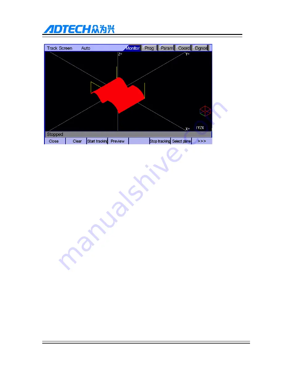
Graphic Simulation Interface 

8.6


Parameter Interface 

The parameter interface shows system parameter info, including comprehensive, axis parameter, management, 

tool magazine, spindle, port, etc. In the main interface, press [parameter] to enter the interface. 

Parameter has the following menus: 

Summary of Contents for CNC9 Series

Page 1: ...ADTECH 9 Series CNC Maintenance Manual ...

Page 2: ...iaobing and Yao Lei with version No A0104 and item number is applicable for all the CNC9 series Copyright Adtech Shenzhen Technology Co Ltd Adtech hereafter is in possession of the copyright of this manual Without the permission of Adtech the imitation copy transcription and translation by any organization or individual are prohibited This manual doesn t contain any assurance stance or implication...

Page 3: ...ng resistance Do not use neutral line N to substitute earth wire Ensure grounding to be correct and solid in order to avoid product failures or unexpected consequences Connect the surge absorption diodes to the product in the required direction otherwise the product will be damaged Ensure the power switch is OFF before inserting or removing plug or disassembling chassis Overhauling Ensure the powe...

Page 4: ...nvironments Add rubber rails as cushion on the place with strong vibration Maintenance Please implement routine inspection and regular check upon the following items under the general usage conditions i e environmental condition daily average 30 load rate 80 and operating rate 12 hours day Routine Inspection Routine Confirm environmental temperature humidity dust or foreign objects Confirm abnorma...

Page 5: ...ual CNC9640 is control systems with different axes and same hardware functions The programs developed on this platform contain M series software for milling machines and L series software for lathes Different software has different functions and masks M series are system for milling machine motion The M or M series mark indicates specific interface or function for milling machine software system L...

Page 6: ...ystem LCD keypad 11 2 2 ADTCNC99 and 98 series system LCD keypad 13 2 3 System menus 15 2 3 1 Autorun 15 2 3 2 Program edit 16 2 3 3 Parameter 16 2 3 4 Work coordinates 17 2 3 5 Diagnosis 18 2 4 Operating keys 19 3 Manual operation 21 3 1 Returning to reference point manually 21 3 2 Each axis returns to reference point separately 21 3 3 Each axis return to reference point simultaneously 21 3 4 Res...

Page 7: ...ool Regulator Parameter 37 3 14 3 Tool setting by test cutting L series 38 3 15 Data settings 38 3 15 1 Tool compensation data settings 38 3 15 2 System parameters setting 39 3 16 System shortcuts 39 4 Automatic Operation 41 4 1 Memory operation 41 4 2 MDI operation 41 4 3 USB disk DNC 41 4 4 Speed rate adjustment 42 4 5 SBK function 42 4 6 BDT function 43 4 7 Stopping automatic operating 43 5 Saf...

Page 8: ... Editing modifying programs 58 7 3 1 Single line copy paste and delete 58 7 3 2 Multi line copy paste and delete 58 7 3 3 Macro function fast programming 58 7 4 Deleting files 59 7 4 1 Deleting files in memory 59 8 Main interfaces of the system 60 8 1 Position Interface 60 8 1 1 Absolute Position 61 8 1 2 Relative Position 62 8 1 3 Comprehensive coordinates 63 8 1 4 Deviation position 63 8 2 Edit ...

Page 9: ...t 80 8 8 5 Screw itch error compensation 80 8 9 Controller diagnosis interface diagnosis 82 8 9 1 Alarm check 82 8 9 2 IO diagnosis interface 82 8 9 3 Function test 82 8 9 4 System Info 83 8 10 Macro variable view interface macro variable 83 8 11 Current mode instruction info 84 9 System maintenance 85 9 1 Restart 85 9 2 System upgrade 85 9 3 Reset 85 9 4 Parameter backup and restore 85 9 5 Enter ...

Page 10: ...rface 9640 series XS8 205 12 2 6 Spindle encoder interface 9640 series XS12 206 12 2 7 RS232 interface 96 series XS9 99 series XS11 RS 485 interface 9810 9650 and RJ45 network interface 9 series 209 12 2 8 USB memory connection interface 96 series XS10 210 12 2 9 PC USB communication interface 96 series XS11 99 series X13 210 11 3 Electrical connection diagram 210 11 3 1 Symbol schematic diagram 2...

Page 11: ...ing diagram 232 12 5 ET202A splitter wiring diagram 236 13 Transmission of Computer NC Program Network to the system 239 13 1 System IP Settings 239 14 Appendix Common Servo Wiring Diagrams 243 14 1 Pulse control port wiring definition 243 14 1 1 Wiring diagram of ADTECH QS QX and Shanyang servo driver 243 14 1 2 Yaskawa Matsushita Fuji TECO 243 ...

Page 12: ...rpolation CNC9650 series 2 axes arc interpolation Input instruction Minimum setting unit 0 001 mm Minimum moving unit 0 001 mm Maximum instruction value 9999 999 mm Feeding Fast feeding speed X axis Y axis Z axis A axis 9999 mm min maximum Feeding speed range Per minute 1 9999 mm min Per rotation 1 500 rpm Automatic acceleration deceleration Yes Feeding speed rate 10 150 Manual Continuous manual f...

Page 13: ... quantity Capacity 2G 100 work areas No limit on processing file quantity Program edit Program edit Insert modify delete cancel Program No sequence No address character retrieval Yes Decimal point programming Yes Display 800 480 pixels 7 LCD 800 600 pixels 8 10 4 LCD CNC9640 9650 CNC9810 9960 Position screen program edit Tool compensation setting alarm display Handwheel test diagnosis screen Param...

Page 14: ...ng environment No excessive dust acid alkali corrosive and explosive gases no strong electromagnetic interference 1 3System function 1 3 1 Self diagnosis function Diagnose CPU memory LCD I O interface parameter state coordinates and processing program comprehensively every time the system is started or reset diagnose power supply spindle limit and I O ports in real time during operating 1 3 2 Comp...

Page 15: ... reference point 1 3 4 Full Chinese menu operation full screen edit 9640 9620 CNC system uses cascading menu structure and full Chinese operation to ensure simple intuitive and convenient operation 1 3 5 Abundant error correction functions Point out the nature and correct the errors in operation 1 3 6 Program exchange between CNC system and PC Perform CAD CAM CAPP auxiliary programming with abunda...

Page 16: ...Note Press the submenu buttons to perform the operations of submenus Manual axis moving and edit input are composite It has different definitions in different modes System working mode switch area is used to switch working modes which can improve the security and system performance Handwheel and single step mode are switched with Repeat button ...

Page 17: ... current window Working mode info shows currently selected working mode System main screen shows current main screen The submenu options are used to switch submenus with left triangle F1 F6 and right triangle The right arrow is used to turn pages and the left arrow is used to close the submenus in next level and previous menu ...

Page 18: ...ADTECH9 Series CNC Maintenance Manual 13 2 2ADTCNC99 and 98 series system LCD keypad ...

Page 19: ...ADTECH9 Series CNC Maintenance Manual 14 ...

Page 20: ...he menus Press a key to show the corresponding content in the bottom of the LCD Key in the left Return to previous menu Key in the right Turn pages to show other menus of same level The main menus of the system include Monitor Prog Edit Parameter Coordinate and Diagnosis Each main menu contains several submenus which are shown below 2 3 1 Autorun ...

Page 21: ...ete Moito Edit edit er or t Po Tr M P 16 osition rack MDI Prog E File ADTE n Edit e ECH9 Series C A Po Relati Com Po P Sele CNC Maintenan Absolut osition ve Pos prehe osition review ect Pla nce Manual te n sition nsive n w ane ...

Page 22: ...2 3 4 Work coo Pa ordinates arameter 17 T ADTE Compr Param A Config Manag Tool M Princip Po ECH9 Series C rehensi meter Axis uration gement agazine pal Axis ort CNC Maintenan ve n t e s nce Manual ...

Page 23: ...Coo rdinates ordina 18 s tes ADTE Co M To M ECH9 Series C Coord Sett ompen Coord Parame Cente Measure ool Reg Measure Comp Tool Test CNC Maintenan dinate ing nsation inate eter ered ement gulator ement pensa Settin t Cutti nce Manual tion ng for ng ...

Page 24: ...ogr Selec Four curso left ri Up D Selec ADTE el alarm reset C r letters numbe irm or cancel op ram edit insert ct operating mod keys are avail or among subs ight Down page up o ct the menus A Inp D DA ECH9 Series C Purpose CNC rs etc peration delete modify de lable Up Dow sections Left R or down Alarm put D Ou Diagn A Dia CNC Maintenan y wn adjust ratio Right move c m Info iagno tput nosis agnos n...

Page 25: ...and press it again to stop rotating Spindle counterclockwise Press to rotate the spindle counterclockwise and press it again to stop rotating Coolant Coolant on off Lubricant Lubricant on off BDT Block delete on off SBK Single block function on off PAUSE Automatic running pauses START Automatic running starts ...

Page 26: ...ng stops You can set the Home mode in Parameter Comprehensive Parameter in which 0 default indicates program and 1 indicates mechanical You can also press SBK key in home mode to switch among Mechanical Program Mechanical quickly This method doesn t conflict with parameter setting You can select accordingly To use servo home as the home signal you need to set Axis phase Z home enable to 1 in Param...

Page 27: ... to show the value of corresponding axis and then press the Cancel key to reset the relative position of current axis Note The tool also can return to reference point according to program instruction i e returning to reference point automatically 0 Caution Generally the system will perform home operation after connecting the power supply If the power fails while the machine tool is moving the syst...

Page 28: ...se increment is moved every time the key is pressed The specific operation is as follows 3 7 1 Single step increment selection After selecting the single step mode the single step movement amount is selected by the five single step increments of 0 001 0 01 0 1 1 0 L by pressing the up down left right direction keys L is set to a manual user defined increment By moving the cursor to L and pressing ...

Page 29: ... select handwheel operation Rotate the dip switch on the handwheel to select handhweel axis X Y Z A Rotate the increment dip switch on the handwheel to select the moving amount 0 1 0 01 0 001 Rotate the handwheel to move the machine tool The tool moves certain distance every time you rotate the handwheel for a scale For example if you select X axis in step and select 0 01 in step the tool moves 0 ...

Page 30: ...the key manual mode mode the key manual mode mode the ke operation k e reverse rota ess the revers 25 n operatio e press this k ey indicator i e press this k y indicator is e press this k y indicator is e press this k y indicator is keys ation are avai se rotation ke ADTE n key to switch s on if only t key to switch s on if only th key to rotate s on if only th key to rotate s on if only th ilable...

Page 31: ...nd L series uses test cutting 3 10 1 Centered M series The centered function is that the system calculates the center position of the workpiece automatically while tool setting to realize segment centered rectangle centered and circle center location Note In the tool setting operation below if the auxiliary parameters of the coordinate system doesn t need setting the first three steps can be omitt...

Page 32: ...ecording all boundary points to calculate the coordinates of center point If there is no question press EOB again to return the result to specified coordinate system Plane circle XY plane centered Circle centered has two modes which are three points and two points with specified radius If the user only types two coordinates in the option of workpiece boundary point and specifies one value for R th...

Page 33: ... press Monitor MDI to enter the MDI interface select edit mode enter program block G55G0X0Y0 if coordinate system G55 is selected while tool setting press Start EOB and the tool moves to workpiece center automatically indicating that three points arc centered properly The validation steps for other tool setting methods are same 3 10 2 Tool regulator setting gauge M series The tool regulator of CNC...

Page 34: ...e and range and blac rdinates C an enable the ot be enabled 29 upplies 24V green lines a ck lines are re oordinates pa tool regulato d ADTE V the black an are respective eversed at tim arameter 2 or and perform ECH9 Series C nd yellow line ly connected me of connect 29 Whether to m the tool set CNC Maintenan es in the abov to the corres tion there wi o enable the t tting operatio nce Manual ve fig...

Page 35: ...the tool regulator is connected to the input number IN20 input 20 and the parameter will become IN 20 The limit input port is also configured to IN 21 in the same way 4 Invert the input detection active level According to the wiring diagram of the tool regulator in the above example the limit and the test switches of such tool regulator are of NC type After connecting the tool regulator properly e...

Page 36: ... limit In the case both the detection and limit switches are of NC type we need to invert the active levels of the input detecting points IN20 and IN21 Parameter Port 047 Input detection active level 00 31 Change the input detection active level of IN20 and IN21 in the input mode After changing the input detection level as shown below press and hold the EOB button until the pop up dialog box disap...

Page 37: ... Series CNC Maintenance Manual 32 5 Tool setting coordinates setting Coordinates Tool setting parameter 07 X coordinates of tool regulator 08 Y coordinates of tool regulator 09 Z coordinates of tool regulator ...

Page 38: ...l This parameter is suitable for the condition where the tool regulator is fixed at a certain position of the machine For the setting method of movable tool block the tool regulator performs tool setting at any point You can set this parameter to 9999 When the system performs tool setting it will scan the tool regulator signal at current point Axis selection symbol of tool regulator Coordinates To...

Page 39: ...workpiece coordinate system Z axis G54 coordinates Mode 2 non standard customization and the offset scale is X Y Z A B C Mode 3 G43 3 10 4 Four point centering 1 Set the coordinate value of workpiece boundary point 1 to point 4 in manual or input mode 2 Move the cursor to Center Calculation Result and automatically calculate the four point to the current column by pressing EOB 3 10 5 Calculate the...

Page 40: ...step mode press the Page Up Page Down key to adjust the step pitch 3 12 Data entry In Manual mode press EOB to enter the current absolute coordinates into the current column In Manual mode press X Y Z to enter the corresponding axis coordinates into the current column In Enter mode press X Number Key and then press EOB to manually modify the data of the corresponding axis 3 13 Update the coordinat...

Page 41: ...will scan the tool regulator signal and after scanning is completed it will subtract the machine coordinate of the workpiece zero from the machine coordinate of the tool setting point In the set offset this parameter can also be input manually For the setting of tool block input thickness of the tool block to the parameter Generally the offset is positive when the workpiece origin is above the too...

Page 42: ...or example the zero coordinate of the workpiece after scanning is 90 the system will then set the coordinate value of 90 to the Z axis in the coordinate system when the Z axis is set and the set coordinate system is the one currently selected in the coordinate setting the length compensation is realized by calling the coordinate system command in the program 0 is the tool setting method by taking ...

Page 43: ...ve the axis and test cutting the workpiece After test cutting turn off the spindle but do not move the axis Select edit mode measure corresponding data and display data press the number keys to enter directly press EOB to calculate and save automatically or press Cancel to exit 0 Caution 1 For tool setting by test cutting automatically calculate the entered measurement value plus current machine t...

Page 44: ...r the value and then press EOB to modify the parameter where the cursor locates 3 16 System shortcuts Numeric Input dialog box has two input methods direct assignment and incremental assignment Direct assignment refers to assigning the entered number directly to the specified parameter and incremental assignment refers to assigning the sum of entered number and current value of the specified param...

Page 45: ...ADTECH9 Series CNC Maintenance Manual 40 ...

Page 46: ...Edit File in the menu or press File on the panel to enter file operation interface Press the direction keys to move the cursor press EOB to select a program and load the file into the work area Press mode selection key Auto to switch to automatic mode Press the Start key to run the program and the indicator is on 4 2MDI operation In Monitor interface switch to MDI enter the program with keypad and...

Page 47: ...ce to adjust the manual rate Press the key to increase or decrease by 10 10 150 If you press the FF key and Up Down key you can adjust the fast forward rate by 10 10 150 Spindle rotation In automatic or manual mode when the spindle rotates normally press the Left Right key to adjust the spindle rotation by 100r min The maximum rotation is set by the spindle parameters in the system and the minimum...

Page 48: ...lock stop and all mode information is saved Start with CNC and the automatic operation can be started again After processing a part the automatic operation stops Program End After executing the block with M30 the automatic operating stops changes into reset state and returns to program start Feeding pause During automatic operation press the Pause key on the operation panel the automatic operation...

Page 49: ...y After investigating the alarm reason press Reset to clear the alarm information 5 3Soft limit over travel If the tool enters the restriction area regulated by the parameter travel limit the system alarms over travel and the tool decelerates and stops At this moment you can move the tool to safe direction in manual mode and then press Reset to release the alarm 0 Caution During automatic operatio...

Page 50: ...tool fails 0007 Tool Invalid 0008 G Program Repeat Error 0009 G Program Number Error 0010 G7X8X Instruction Run Error 0011 Appointed Port Number Error 0012 Program Abend 0013 Appointed M01 Instruction Stop 0014 Appointed Program Number Nonentity 0015 M98 Format Error 0016 Motion Run Error 0017 Current Program No Repair 0018 G Program Format Error 0019 M99 Instruction Abort 0020 Motion Abort 0021 I...

Page 51: ...ssing T Code Error 0042 Missing S Code Error 0043 Missing P Code Error 0044 Missing M Code Error 0045 Missing G Code Error 0046 Missing I Code Error 0047 Missing J Code Error 0048 Missing K Code Error 0049 Missing Q Code Error 0050 Screw Value Repeat Error 0051 System Abort 0052 System Reset exits 0053 No G code parameter source 0054 No store address for G code program number form 0055 Macro funct...

Page 52: ...f the next track of the radius compensation overlaps 0073 Compensation value of radius compensation greater than the R value ofG0203 0074 Code group not supported in radius compensation 0075 Excessive NURBS nodes 0076 NURBS parameter error 0077 Overflow error due to excessive segments of compound program memory program 0078 Compound program expression error 0079 No U command error 0080 No W comman...

Page 53: ...heck corresponding limit sensor point or parameters If hard limit occurs and the appearance of the sensor point doesn t have any problem enter the diagnosis mode in manual mode and check the state of the input port in diagnosis mode If the state is valid please eliminate in sequence Pull out the input IO cable and check whether the induction disappears If yes please check the circuit If the proble...

Page 54: ...tedly 1047 Spindle not reset 1048 Mold not clamped 1049 Safety signal can t be detected 1051 Air pressure insufficient 1052 System material clamping signal invalid alarm 1053 System filling machine oil pressure alarm 1054 Spindle alarm 1055 Inverter alarm 1056 Tool placement failure 1057 Tool grabbing failure 1058 Magazine door detection error 1059 Detent detection error 1060 Tool releasing detect...

Page 55: ...o driver alarm 1085 C Servo driver alarm 1086 Cumulative number of workpieces exceeds the maximum set limit 1087 Spindle overcurrent alarm 1088 X1 direction soft limit 1089 X1 direction soft limit 1090 Y1 direction soft limit 1091 Y1 direction soft limit 1092 X1 direction hard limit 1093 X1 direction hard limit 1094 Y1 direction hard limit 1095 Y1 direction hard limit 1096 X1 Servo driver alarm 10...

Page 56: ... C1 Servo driver alarm 1118 Channel 2 not zeroed 1119 Motion library abnormal alarm code system restart required 1120 Bus servo disconnected axis number system restart required 1121 Bottom motion target position data exception 110 1122 EtherCAT bus communication failure 118 1123 Axis alarm 119 1124 System alarm 17 1125 System alarm 18 1126 System alarm 19 1127 System alarm 20 1128 System alarm 21 ...

Page 57: ...er to the alarm info in the Diagnosis menu for details When the alarms are eliminated please press Reset to clear the alarm ring 6 4Self diagnosis function The CNC system may stop even when there is no alarm info this may be because the system is executing certain processes Please check with the self diagnosis function The steps of self diagnosis are as follows 1 In the main menu press Diagnosis t...

Page 58: ... the memory and load into the system by default Select Close to exit Edit interface In edit mode enter the program content After editing all programs press Reset to save the edited programs into the system memory 7 1 2 Computer network access serial port input Connect the controller to the router with a network cable Through built in command window it is available to view the local computer ip add...

Page 59: ...ADTECH9 Series CNC Maintenance Manual 54 Check whether the network is connected through the ping command in the command window on the computer as shown in the following figure ...

Page 60: ...is not connected Check whether the IP address is correctly assigned whether there is any problem with the connection and whether the system is powered on When the network is normal you can open the communication software add the terminal configuration and set the IP address as shown below ...

Page 61: ...fter setting the correct IP address select the station number 1 under the TCP extension menu bar and click the Connect button to access the contents of the controller as shown below Select to upload and download files in the file management bar ...

Page 62: ... PROG directory in disk D enter the directory and select Paste to complete copying 7 2Reading programs into work area 7 2 1 Reading programs from controller into work area The steps of loading files from system memory into work area are as follows Press File to enter file operation interface Select desired program which is in PROG directory in disk D by default press EOB to enter subdirectory or p...

Page 63: ...ine copy paste and delete Move the cursor to the starting line to be copied and then press Segment Copy F4 the prompt box Please move the cursor to the end of the segment to be copied and press Enter for confirmation pops up press OK EOB and close the prompt box According to the prompt move the cursor to the end of the segment of the program you want to copy and press the Enter button to complete ...

Page 64: ...aution After all operations press Reset to save the files and the edit functions base on edit mode CNC96XX uses new file mapping technology and allows loading processing files that exceed its memory Therefore to ensure the system efficiency you can only search and process but can t edit the processing files that exceed 2MB 7 4Deleting files 7 4 1 Deleting files in memory Follow the steps below to ...

Page 65: ...a ition interface Po Main in e ent machine t ain interface p e is as follow osition 60 terfaces tool coordina press Monito s Co ADTE s of the s ates including or to enter th Absolu Relativ omprehe Offse ECH9 Series C system g absolute po he position in ute ve ensive et CNC Maintenan osition relativ nterface nce Manual ve position an nd ...

Page 66: ...aintenance Manual 61 8 1 1 Absolute Position The position of current machine tool coordinates relative to the origin of workpiece coordinate system The absolute position interface is as follows Absolute position interface ...

Page 67: ...etting Considering that some operators have been used to manual calculation this function is preserved With more and more powerful automatic centered function it is less used The operation is as follows Enter Position interface Switch to Relative interface Then enter manual mode Press a coordinate axis No e g X and the X coordinate flashes Press Cancel to reset X coordinate to 0 The relative posit...

Page 68: ...nce Manual 63 8 1 3 Comprehensive coordinates The interface displayed by absolute coordinates and machine tool coordinates Comprehensive position interface is shown below Comprehensive Position Interface 8 1 4 Deviation position ...

Page 69: ... moveme point This valu f the screw is 1 ere may be an e loosen the coup his method unti current work Prog edi New Teac Save File Gram Chec CAM ADTE ent from speed r ue takes about h 0MM and afte error of one turn pling to rotate t il the requireme area In the ram t w ch e as e mmar ck M ECH9 Series C reducing switch half of the motor er it returns to z n after being ze the motor lock ents are sat...

Page 70: ...w program file by pressing the corresponding F1 key and a dialog box will pop up requiring entering the file name enter the file name and press the EOB key to create the file when there will be a prompt asking to load the file then press Edit to edit the program 8 2 3 Save as By saving the file as a copy and modifying on this copy thus realizing the quick similar product program editing 8 3MDI int...

Page 71: ...Mon ter complete rectly t settings qui face is shown nito NC code ins ickly press a n below r 66 struction in e and hold the MDI Interf ADTE dit mode pre Reset key f face MD ECH9 Series C ess the Start for three seco DI CNC Maintenan t key in the onds and cho nce Manual edit mode an oose to reset o nd or ...

Page 72: ...he USB ce is shown b T t you can mana e ollowing func opy the files b opy the upgra le Manageme arting due to ke certain fun cable and ex below F 67 age the system ctions between USB ade file to sy ent interface power failur nction take eff xchange the d File Operation I Fi ADTE m files B disk and ele stem memory e press the R re In certain ffect data between nterface le ECH9 Series C ectronic dis...

Page 73: ...e compu position r two ends flat is ion C processing p ace l time track d time In stand n are as shown nit is the set p own below tor 68 copy the selecte his allows file in copy the select his allows file in uter You select It realizes the t s used to conne program display autom dby mode yo n below pixel unit Tra ADTE ed file to the clip nteraction ted file to the cl nteraction the files copied tr...

Page 74: ... Interface 8 6Parameter Interface The parameter interface shows system parameter info including comprehensive axis parameter management tool magazine spindle port etc In the main interface press parameter to enter the interface Parameter has the following menus ...

Page 75: ... Pa aramete ers 70 C T ADTE Compre A Config Manag Tool M Spri Po ECH9 Series C ehensiv Axis uration gement agazine ndle ort CNC Maintenan ve n t e nce Manual ...

Page 76: ...anual 71 8 6 1 Comprehensive Parameter Comprehensive parameters are a set of functions that aren t classified in details e g home mode manual speed etc Comprehensive parameter interface is shown below Comprehensive Parameter Interface ...

Page 77: ... 72 8 6 2 Axis parameters Axis parameters are a set of parameters of interface characteristics of control position axis Please refer to the parameter description for details Axis parameter interface is shown below Axis Parameter Interface ...

Page 78: ...Series CNC Maintenance Manual 73 8 6 3 Management Parameter This is a function set that confirms identity and initializes the system Management parameter interface is shown below Management Parameter Interface ...

Page 79: ... should refer to the instructions provided by the machine tool manufacturer 8 6 5 Spindle parameters Spindle parameters are the set of electrical characteristics of servo and common spindles The specific application also depends on the spindle selection of the machine tool manufacturer The servo parameters and axis parameters have the same meaning and therefore please refer to the description of a...

Page 80: ...n interfa es co parameters he assignment ion numbers ng of the para ace is shown b IO Conf nterface ws tool comp er input varia low ace oordi 75 s t of hardware which will i ameters below figuration Param ensation info ables The com nates ADTE e interfaces T improve the s meters Interface o of the syste mpensation m s ECH9 Series C This paramete system flexib e em including method is dif Com CNC M...

Page 81: ...ool Compen workpiece oordinate sys ess Coordina nate system tem i e the o inate systems tem interface inates 76 o compensatio G44 and G4 ation number es nsation Parame e coordina stem info inc ate to enter c m offset of wor s G54 G59 e ADTE on variables 1 G42 ente r in NC prog ter Setting Inter ate system cluding settin coordinate sy rkpiece zero p and nine ext Coo sett ECH9 Series C i e tool len ...

Page 82: ...e work co kpiece coordi oordina inate system ates interface is sh Workpiece C 77 hown below Coordinate Syste Co se ADTE em Setting Inter oordina ettings ECH9 Series C rface ate s CNC Maintenan nce Manual ...

Page 83: ...set nates offset inates of tool re nates of tool re nates of tool reg nates of tool re nates of tool re nates of tool re ection symbol o automatically a ulator machine ulator machine ulator machine ulator machine ulator machine ulator machine ulator X search ulator Y search ulator Z search ulator A search ulator B search ulator C search et to coordinate ulator scanning e the tool regul ulator scan...

Page 84: ...ece 2 Tool regulator coordinates effective signal automatic tool setting machine tool Z negative limit of tool regulator The X Y coordinates are the mechanical coordinates of the tool regulator on machine tool the tool regulator can position automatically only when the coordinate is set properly Effective voltage level of tool regulator is to set the signal interface level of the tool regulator wh...

Page 85: ...TECH9 Series CNC Maintenance Manual 80 8 8 4 Offset It can be used for the irregularly fixed magazines Each tool placement position of each axis can be set individually 8 8 5 Screw itch error compensation ...

Page 86: ...ADTECH9 Series CNC Maintenance Manual 81 Input the compensation number by referring to the screw bidirectional error compensation table of each axis ...

Page 87: ...ng IO and p A spindle fi eter optimiza nput the act f spindle the is 82 face diag e hardware in function test larm includin n check curre press EOB to iction and ha ation of relat tually measu system will c O ADTE gnosis nterfaces of s and system i ng 15 alarm r ent IO state o control the o andwheel Co ted function ured voltage correct accord Ala Input Output Exten Funt Syste ECH9 Series C system ...

Page 88: ... ble register dir rface ht levels as be f different le lly and show cal variable s omize the nam ames have v For the writ manual 83 current syst erface you ca nterface cro function rectly in edit elow vels you ca ws the variab submenu and mes of 20 var isual meanin ting and use o V ADTE tem and is u an follow the macro va In this menu mode an check the bles of curren d then select a riables 100 ng...

Page 89: ...itor interface you can check the running code info of current system Motion instruction G00 G01 Select plane G17 G18 G19 Coordinate logic G90 G91 Workpiece coordinate system G54 G59 G591 G599 Radius compensation G40 G41 G42 Length compensation G43 G44 G49 Compound instruction retracting plane G98 G99 Spindle rotation S Tool No T ...

Page 90: ...ADT directory in disk C and paste it Select the second upgrade file NC_RES NC skip this step if the file doesn t exist Also select Copy enter disk C and paste it in directory ADT 6 After upgrading enter BIOS select Boot up mode to startup and restart the system to validate the program in disk D 7 Enter System Info in Diagnosis menu to view the system version and compilation date and check whether ...

Page 91: ...oot directory of disk D The system will recognize this file automatically in the process of restoring 9 5Enter BIOS 1 If the system has irreversible error and can t be started please enter BIOS to upgrade and maintain the program 2 To enter BIOS press the Cancel key after the controller is electrified and before the application is started after entering a blue background interface pops up If the B...

Page 92: ... the operator password in P3 1 in management parameters the system will enter the corresponding mode automatically according to the entered password 2 According to the application the parameters will take effect immediately or after restarted the parameters that require restart are marked with 3 Certain parameters are set in binary system parameter descriptor has bit symbol the conversion between ...

Page 93: ...ber increment Instant Comprehensive parameter P1 012 UARTO string baud rate Restart Comprehensive parameter P1 013 Controller ID number Restart Comprehensive parameter P1 014 Arc interpolation feed mm Instant Comprehensive parameter P1 015 G73 M circulating tool retraction amount mm Instant Comprehensive parameter P1 016 G83 M circulating tool retraction amount mm Instant Comprehensive parameter P...

Page 94: ...T code form compensation number digit Instant Comprehensive parameter P1 036 Local IP address Restart Comprehensive parameter P1 037 Subnet mask Restart Comprehensive parameter P1 038 Default gateway Restart Comprehensive parameter P1 039 MAC address Restart Comprehensive parameter P1 040 No this parameter Instant Comprehensive parameter P1 041 Feed speed setting Enable Instant Comprehensive param...

Page 95: ...amming coordinates calculation conversion Instant Comprehensive parameter P1 060 4 axis max rotate speed Instant Comprehensive parameter P1 061 Handwheel encoder dir Instant Comprehensive parameter P1 062 Handwheel control mode 0 old Instant Comprehensive parameter P1 063 Handwheel max rate Instant Comprehensive parameter P1 064 Handwheel acceleration Kps Instant Comprehensive parameter P1 065 Mac...

Page 96: ...ud rate Restart Comprehensive parameter P1 082 Local IP address 2 Restart Comprehensive parameter P1 083 MAC address 2 Restart Comprehensive parameter P1 084 Low voltage interrupt enable 0 off 1 on Restart Axis parameter P2 001 X Gear Numerator Restart Axis parameter P2 X Gear Denominator Restart Axis parameter P2 Y Gear Numerator Restart Axis parameter P2 Y Gear Denominator Restart Axis parameter...

Page 97: ...arameter P2 B axis acceleration Kpps Instant Axis parameter P2 C axis acceleration Kpps Instant Axis parameter P2 005 X Soft PosLimit mm Instant Axis parameter P2 X Soft NegLimit mm Instant Axis parameter P2 Y Soft PosLimit mm Instant Axis parameter P2 Y Soft NegLimit mm Instant Axis parameter P2 Z Soft PosLimit mm Instant Axis parameter P2 Z Soft NegLimit mm Instant Axis parameter P2 A Soft PosLi...

Page 98: ... Instant Axis parameter P2 009 X Server Enable Output Port No Instant Axis parameter P2 Y Server Enable Output Port No Instant Axis parameter P2 Z Server Enable Output Port No Instant Axis parameter P2 AServer Enable Output Port No Instant Axis parameter P2 B Server Enable Output Port No Instant Axis parameter P2 C Server Enable Output Port No Instant Axis parameter P2 010 X Server Alarm Input Por...

Page 99: ...14 X Home Dir Instant Axis parameter P2 Y Home Dir Instant Axis parameter P2 Z Home Dir Instant Axis parameter P2 A Home Dir Instant Axis parameter P2 B Home Dir Instant Axis parameter P2 C Home Dir Instant Axis parameter P2 015 X axis home speed mm min Instant Axis parameter P2 Y axis home speed mm min Instant Axis parameter P2 Z axis home speed mm min Instant Axis parameter P2 A axes home speed ...

Page 100: ...in rate mm s Instant Axis parameter P2 B max restrain rate mm s Instant Axis parameter P2 C max restrain rate mm s Instant Axis parameter P2 019 X_Servo Alarm ELevel Instant Axis parameter P2 Y_Servo Alarm ELevel Instant Axis parameter P2 Z_Servo Alarm ELevel Instant Axis parameter P2 A_Servo Alarm ELevel Instant Axis parameter P2 B_Servo Alarm ELevel Instant Axis parameter P2 C_Servo Alarm ELevel...

Page 101: ... parameter P2 Z Limit ELevel Instant Axis parameter P2 4 Limit ELevel Instant Axis parameter P2 B Limit ELevel Instant Axis parameter P2 C Limit ELevel Instant Axis parameter P2 024 X Pulse Mode Restart Axis parameter P2 Y Pulse Mode Restart Axis parameter P2 Z Pulse Mode Restart Axis parameter P2 A Pulse Mode Restart Axis parameter P2 B Pulse Mode Restart Axis parameter P2 C Pulse Command Format ...

Page 102: ...hysial Assign Num Restart Axis parameter P2 B physial Assign Num Restart Axis parameter P2 C Physial Assign Num Restart Axis parameter P2 029 X encoder line number p Instant Axis parameter P2 Y encoder line number p Instant Axis parameter P2 Z encoder line number p Instant Axis parameter P2 A encoder line number p Instant Axis parameter P2 B Encoder line number p Instant Axis parameter P2 C Encode...

Page 103: ...age Instant Axis parameter P2 B Rolling Display Usage Instant Axis parameter P2 C Rolling Display Usage Instant Axis parameter P2 034 X G00 Rolling Path Optimize Instant Axis parameter P2 Y G00 Rolling Path Optimize Instant Axis parameter P2 Z G00 Rolling Path Optimize Instant Axis parameter P2 A G00 Rolling Path Optimize Instant Axis parameter P2 B G00 Rolling Path Optimize Instant Axis parameter...

Page 104: ...coder Logic Dir Instant Axis parameter P2 B Encoder Logic Dir Instant Axis parameter P2 C Encoder Logic Dir Instant Axis parameter P2 039 X axis return to zero 2nd segment leave speed Instant Axis parameter P2 Y axis return to zero 2nd segment leave speed Instant Axis parameter P2 Z axis return to zero 2nd segment leave speed Instant Axis parameter P2 A axis return to zero 2nd segment leave speed ...

Page 105: ...xis parameter P2 B axis screw interpolation enable Instant Axis parameter P2 C axis screw interpolation enable Instant Axis parameter P2 042 X axis screw interpolation pitch mm Instant Axis parameter P2 Y axis screw interpolation pitch mm Instant Axis parameter P2 Z axis screw interpolation pitch mm Instant Axis parameter P2 A axis screw interpolation pitch mm Instant Axis parameter P2 B axis scre...

Page 106: ...m Instant Axis parameter P2 C axis screw interpolation end position mm Instant Axis parameter P2 045 X servo device address Instant Axis parameter P2 Y servo device address Instant Axis parameter P2 Z servo device address Instant Axis parameter P2 A servo device address Instant Axis parameter P2 B servo device address Instant Axis parameter P2 C servo device address Instant Axis parameter P2 046 X...

Page 107: ...eter P2 Z Servo Driver Type Restart Axis parameter P2 A Servo Driver Type Restart Axis parameter P2 B Servo Driver Type Restart Axis parameter P2 C Servo Driver Type Restart Axis parameter P2 049 X encoder type Restart Axis parameter P2 Y encoder type Restart Axis parameter P2 Z encoder type Restart Axis parameter P2 A encoder type Restart Axis parameter P2 B encoder type Restart Axis parameter P2...

Page 108: ...e control output port number Instant Axis parameter P2 C servo pulse control output port number Instant Axis parameter P2 052 X servo rigid tapping mode output port number Instant Axis parameter P2 Y servo rigid tapping mode output port number Instant Axis parameter P2 Z servo rigid tapping mode output port number Instant Axis parameter P2 A servo rigid tapping mode output port number Instant Axis...

Page 109: ...dle quasi stop in position input port number Instant Axis parameter P2 A servo spindle quasi stop in position input port number Instant Axis parameter P2 B servo spindle quasi stop in position input port number Instant Axis parameter P2 C servo spindle quasi stop in position input port number Instant Axis parameter P2 055 X servo spindle zero speed in position input port number Instant Axis parame...

Page 110: ...password to select management mode Instant Management parameter P3 002 Edit super user password Instant Management parameter P3 003 Edit operation user password Instant Management parameter P3 004 Initialize comprehensive parameters to default Restart Management parameter P3 005 Initialize IO configuration to default Restart Management parameter P3 006 Reset all parameters Restart Management param...

Page 111: ... parameter P3 023 M Macro Program Selection Restart Management parameter P3 024 T Macro Program Selection Restart Management parameter P3 025 PLC program enable Restart Management parameter P3 026 Screen Saver ON Instant Management parameter P3 027 Modbus master slave setting Restart Management parameter P3 028 Imperial system enable Restart Management parameter P3 029 Additional panel baud rate R...

Page 112: ...Mechanical spindle speed in gear 1 rpm Instant Spindle parameters P5 012 Mechanical spindle speed in gear 2 rpm Instant Spindle parameters P5 013 Mechanical spindle speed in gear 3 rpm Instant Spindle parameters P5 014 Mechanical spindle speed in gear 4 rpm Instant Spindle parameters P5 015 Spindle stop delay ms Instant Spindle parameters P5 016 Alarm off spindle enable Instant Spindle parameters ...

Page 113: ...tapping adjusting parameter Kd Instant Spindle parameters P5 033 Tapping adjusting parameter K2 Instant Spindle parameters P5 034 Delay before tapping Instant Spindle parameters P5 035 Tapping hole bottom delay Instant Spindle parameters P5 036 If tapping collects data Instant Spindle parameters P5 037 Maximum allowable tapping error Instant Spindle parameters P5 038 Tapping fixed cycle type Insta...

Page 114: ...t Port parameter P6 020 Spindle CW 2 forward output port number Instant Port parameter P6 021 Spindle CCW 2 reverse output port number Instant Port parameter P6 022 Spindle inverter alarm reset output Instant Port parameter P6 023 Spindle blowing output port Instant Port parameter P6 024 Spindle brake output port Instant Port parameter P6 029 Safety grating input port number Instant Port parameter...

Page 115: ...tect ELevel 32 63 Instant Port parameter P6 049 Input Detect ELevel 64 95 Instant Port parameter P6 050 Input Detect ELevel 96 127 Instant Port parameter P6 051 Input Detect ELevel 128 159 Instant Port parameter P6 052 Input Detect ELevel 160 191 Instant Port parameter P6 053 Input Detect ELevel 192 223 Instant Port parameter P6 054 IO Conf in RESET 00 31 Instant Port parameter P6 055 IO Conf in R...

Page 116: ...ameter P6 074 Power on Output Open 192 223 Instant Port parameter P6 075 Wheel 0 1 Instant Port parameter P6 076 Wheel 0 01 Instant Port parameter P6 077 Wheel 0 001 Instant Port parameter P6 078 X Wheel Instant Port parameter P6 079 Y Wheel Instant Port parameter P6 080 Z Wheel Instant Port parameter P6 081 A Wheel Instant Port parameter P6 082 B Wheel Instant Port parameter P6 083 C Wheel Instan...

Page 117: ...by accidental speed programming error when calling processing files 004 Zero Return Mode Range 0 1 Unit None Authority Operation admin or higher Default 0 Program home Effective time Instant Note 0 Program home 1 Mechanical home Program home is that the coordinates go to home i e in place Mechanical home requires external detection switch to locate the home position while home operation move to sp...

Page 118: ...cates no filter 006 Selection of communication mode restart Range No User Network Uart All User Unit None Authority Operation admin or higher Default Uart Effective time Restart Note NetTCP Uart0 Uart1 NetUDP Uart3 008 Zeroing soft limit no alarm enables Range 0 1 Unit None Authority Operation admin or higher Default 0 Effective time Instant Note No soft limit detection required when zeroing 009 U...

Page 119: ...increment Range 0 64 Unit None Authority Operation admin or higher Default 0 Effective time Instant Note While editing G code manually add a line number Nxxxxx automatically in a new line 0 indicates that this function is disabled 012 UART serial port baud rate Range 9600 115200 Unit None Authority Operation admin or higher Default 115200 Effective time Restart Note The communication rate setting ...

Page 120: ...use during processing obvious and affecting the processing effect 015 G73 M Loop Obligate mm 016 G83 M Loop Obligate mm Range 0 1 100 Unit mm Authority Operation admin or higher Default 2 000 Effective time Instant Note Set the tool retracting amount after Q is fed in G73 and G83 instructions this parameter default 2mm is set according to actual chip removal effect 017 Arc interpolation processing...

Page 121: ...test In pretreatment mode the system enters processing state buffs for two seconds and pre reads The pretreatment mode only can check the direction and size of feeding segment to adjust the speed automatically and process at optimized speed 020 O Pro Scan Range 0 1 Unit None Authority Operation admin or higher Default 1 Effective time Instant Note File scanning symbol will quicken the file transfe...

Page 122: ... is the rotation set by the user and MaxRPM is the maximum rotation of spindle set by the parameter P4 017 In switching quantity mode constitute block 0 15 according to four digit code to output S code value is restricted to 0 15 022 Lubricant Pressure Open min 023 Lubricant Pressure Keep sec 024 Lubricant Pressure Out Freq Hz Range Unit Authority Operation admin or higher Default 0 Effective time...

Page 123: ... axis up to three sections can be set 026 Arc speed for Radii 027 Arc speed for Speed Range Unit Coefficient Authority Operation admin or higher Default 50 100 Effective time Instant Note Used to restrict the arc processing speed automatically This parameter is valid in pretreatment mode The bigger the radius coefficient is the lower the arc speed is The bigger the acceleration coefficient is the ...

Page 124: ...031 HOME check enable for alarm 032 HOME Check Enable Range 0 1 Unit Authority Operation admin or higher Default 0 1 Effective time Instant Note Used to set whether prompt user to reset under certain conditions ensuring that the user has performed the operation If the value is set to 0 it won t check and will run directly 033 X diameter prog enable L series Range 0 1 Unit Authority Operation admin...

Page 125: ...umber digits L series Range 0 2 Unit Authority Operation admin or higher Default 2 L series Effective time Instant Note Used to set the T value in tool change instruction on lathe controller L series the latter digits indicate the compensation number In some conventional programming people usually use two digits to specify the compensation number used by corresponding tool number For example T0801...

Page 126: ...e the broadcast in the network and regular query of windows will block the network communication of NC 040 This parameter is invalid Standby 041 Feed speed setting En Range 0 1 Unit Authority Operation admin or higher Default 0 Effective time Instant Note This parameter is used to modify the interpolation speed in programming making F programming invalid Used for the cases that processing codes re...

Page 127: ...safe altitude 045 Pause A to safe altitude Range OFF workpiece coordinates machine tool coordinates Unit Authority Operation admin or higher Default 0 Effective time Instant Note OFF turn off this function ON turn on this function when turned on press the Pause key during code processing or execute home operation in home mode Z axis or A axis lifts to the safe altitude set by P1 049 or P1 050 auto...

Page 128: ...ate system press MAC Coord to clear machine coordinates and press G54 Coord to clear G54 workpiece coordinates This function is generally used for machine debugging Do not use it if the machine has been debugged 049 Z axis safe height 050 A axis safe height Range 9999 999 9999 999 Unit mm Authority Operation admin or higher Default 0 Effective time Instant Note When P1 044 or P1 045 is enabled and...

Page 129: ...slide amount V L series Range 0 100 Unit mm Authority Operation admin or higher Default 0 Effective time Instant Note To set the pitch length of acceleration segment of lathe CNC4620 system thread cutting command G32 G92 pitch length of the deceleration segment and run out amount For details of G32 G92 instruction see CNC4620 programming manual 056 Reserved Range OFF ON Unit None Authority Operati...

Page 130: ...min Default 1000 Effective time Instant Note Used to set the delay between actions of the spindle brake switch 059 This parameter is invalid currently Range Unit Authority Operation admin Default Effective time Instant Note This parameter is invalid currently 060 4 axis max rotate speed Range 1 500 Unit Authority Operation admin Default 50 Effective time Instant Note When P1 018 is set to Angle X ...

Page 131: ...ing 0 positive direction 1 negative direction 062 Handwheel control mode Range 0 1 Unit Authority Operation admin Default 0 Effective time Instant Note Used to set handwheel to control the motion of each axis 0 old 1 new 063 Handwheel max rate Range 500 10000 Unit Authority Operation admin Default 4000 Effective time Instant Note Used to set the maximum rate of handwheel valid when P1 062 is set t...

Page 132: ...inate system zero point after machining program operation completes 066 Feeding rate variation Range 1 100 Unit Authority Operation admin Default OFF Effective time Instant Note To set the adjusting unit amount of feedrate 067 Auto chamfering and arc chamfering enable Range OFF Auto chamfering Auto arc chamfering Arc chamfering error Unit Authority Operation admin Default OFF Effective time Instan...

Page 133: ...of double drive zero return to zero mm Range 0 1 10000 Unit Authority Operation admin Default 1 000 Effective time Instant Note To set the machine of double drive gantry structure the maximum deviation of the two servo return to zero synchronization error alarm 071 G code loading boundary scan enable Range OFF ON Unit Authority Operation admin Default OFF Effective time Instant Note To set whether...

Page 134: ...peration admin Default 100 Effective time Instant Note To set the moving speed for positioning the A axis to a safe height when pause or jump the specified line 075 Z Axis Feed Speed Limit mm min Range 0 20000 Unit Authority Operation admin Default 0 Effective time Instant Note To set the total G01 feedrate for the Z axis machining process 076 AAxis Feed Speed Limit mm min Range 0 20000 Unit Autho...

Page 135: ...timeout to access the remote Modbus slave when the system is used as a Modbus master 080 Modbus master retransmission times Range 0 100 Unit Authority Operation admin Default 10 Effective time Instant Note To set the communication retransmission times to access the remote Modbus slave when the system is used as a Modbus master 081 UART3 serial port baud rate Range 9600 115200 Unit Authority Operat...

Page 136: ...ult 0 Effective time Instant Note To set the physical MAC address of the Channel 2 RJ45 network port of the system 084 LV interrupt enable 0 off 1 on Range Unit Authority Operation admin Default 1 Effective time Restart Note 10 3 Axis parameter configuration P2 001 X Gear Numerator X Gear Denominator Y Gear Numerator Y Gear Denominator Z Gear Numerator Z Gear Denominator A Gear Numerator A Gear De...

Page 137: ...io denominator P Pulses corresponding to one rotation of the motor L Machine tool movement corresponding to one rotation of the motor mm CMD CMR is the pulse equivalent actually i e the motion distance corresponding to every pulse unit 0 001mm Ex 1 the motor rotates one cycle every 5000 pulses and the machine tool moves 5mm when the motor rotates one cycle then CMR CMD 5000 5 1000 1 1 Then CMR 1 C...

Page 138: ... 3000 200 1500 Effective time Instant Note This parameter is the trapezoid acceleration deceleration setting and used for GOO instruction About start speed 1 2 rotation motor speed is recommended for step motor as above the machine tool moves 5mm when the motor rotates one cycle and the speed is 5 10mm sec 300 600mm min For servo motor the start and stop shouldn t have vibration If this speed is t...

Page 139: ... limit to 9999 999 If hard limit switch isn t installed please use soft limit which uses machine tool coordinate system as the base point Positive limit and negative limit are subject to actual distance unit mm Since soft limit decelerates and stops at the limit point it may exceed the set distance which depends on acceleration time and speed Please keep certain margin when setting this parameter ...

Page 140: ...on admin or higher Default 0 Effective time Instant Note To set the positive hard limit input port number of each axis 008 X Ext Home Input Port No Y Ext Home Input Port No Z Ext Home Input Port No A Ext Home Input Port No B Ext Home Input Port Number C Ext Home Input Port Number Range 0 8888 Unit None Authority Operation admin or higher Default 0 Effective time Instant Note To set the external ze...

Page 141: ... Input Port No Z Server Alarm Input Port No A Server Alarm Input Port No B Server Alarm Input Port No C Server Alarm Input Port No Range 0 8888 Unit Authority Operation admin or higher Default 0 Effective time Instant Note To set the input signal port number of receiving detection servo alarm 011 X Server Reset Output Port No Y Server Reset Output Port No Z Server Reset Output Port No A Server Res...

Page 142: ...20000 Unit Pulse Authority Operation admin or higher Default 0 Effective time Instant Note Compensate the clearance between control axis Compensate with the pulse in minimum unit The specific number should be converted according to gear ratio 013 X HOME Offset Y HOME Offset Z HOME Offset A HOME Offset B HOME Offset C HOME Offset Range 9999 9999 Unit Pulse mm Authority Operation admin or higher Def...

Page 143: ...A axis Home Dir B axis Home Dir C axis Home Dir Range 0 1 Unit None Authority Operation admin or higher Default 1 1 0 0 Effective time Instant Note Set the mechanical home direction of every processing axis Positive Negative 015 X axis home speed Y axis home speed Z axis home speed A axes home speed B axis home speed C axis home speed Range 0 9999 Unit mm min Authority Operation admin or higher De...

Page 144: ...rs 003 004 017 X axis corner speed smoothing level Y axis corner speed smoothing level Z axis corner speed smoothing level A axis corner speed smoothing level B axis corner speed smoothing level C axis corner speed smoothing level 018 X axis max restrain rate mm sec Y axis max restrain rate mm sec Z axis max restrain rate mm sec A axis max restrain rate mm sec B axis max restrain rate mm sec C axi...

Page 145: ...vel Y_Servo AlarmIn ELevel Z_Servo AlarmIn ELevel A_Servo Alarm ELevel B_Servo Alarm ELevel C_Servo Alarm ELevel 020 X_Servo Reset Out ELeve Y_Servo Reset Out ELeve Z_Servo Reset Out ELeve A_Servo Reset Out ELevel B_Servo Reset Out ELevel Range 0 1 Unit LOGIC VOLTAGE LEVEL Authority Super Admin Default 0 1 Effective time Instant Note Adapt to the interface parameters of selected servo driver pleas...

Page 146: ...ore it is recommended to enable this function for servo motor Step motor doesn t have encoder and can t enable this option or else the signals can t be scanned during mechanical home operation and will move constantly 022 X_ECZ Home ELevel Y_ECZ Home ELevel Z_ECZ Home ELevel A_ECZ Home ELevel B_ECZ Home ELevel C_ECZ Home ELevel Range 0 1 Unit LOGIC VOLTAGE LEVEL Authority Super Admin Default 0 Eff...

Page 147: ...well as interrupted limit However in most cases at 10mm min processing speed it can meet the requirement on processing safety check The hardware response function of hard limit is prior to scanning response function i e if the hardware response is enabled it will quicken the response speed directly It should be noted that the hardware response function only can stop pulse in instant mode Therefore...

Page 148: ...ode restart Y Pulse Logic Dir Mode restart Z Pulse Logic Dir Mode restart 4 Pulse Logic Dir Mode restart B Pulse Logic Dir Mode restart C Pulse Logic Dir Mode restart Range 0 1 Unit None Authority Super Admin Default 1 Effective time Restart Note Set pulse direction if the controller direction is reverse to actual driver direction please modify this parameter to adjust the rotation direction of mo...

Page 149: ...sed to prevent the logic counting of axis exceeding the maximum counting range 2147483648 and causing overflow error Generally overflow occurs only when the axis is set to rotary The system will calculate the corresponding pulse limit according to the gear ratio of current axis and assign to the ROUND parameter of corresponding axis if current axis is set to rotary and uses 360 display mode after ...

Page 150: ... replace the axis through this function For example set P2 045 to 4 P2 048 to 1 then any operation to X axis will be the operation to A axis encoder port on the shell 0 no such axis 1 6 corresponding to 1 6 axis 029 X axis encoder wire number Y axis encoder wire number Z axis encoder wire number A axes encoder wire number B axis encoder wire number C axis encoder wire number Range 0 9999 Unit Wire...

Page 151: ... restart Y Pulse Logic Level restart Z Pulse Logic Level restart A Pulse Logic Level restart B Pulse Logic Level restart C Pulse Logic Level restart Range 0 1 Unit LOGIC VOLTAGE LEVEL Authority Super Admin Default 0 Effective time Restart Note Set the normal voltage level when the pulse is working If the setting is different from the normal voltage level required by motor driver a direction will h...

Page 152: ... axis 1 Linear axis The setting of this parameter and P2 027 axis will affect the setting of P2 021 Please refer to the parameter description of P2 021 for details 033 X Rolling Display Mode Y Rolling Display Mode Z Rolling Display Mode A Rolling Display Mode B Rolling Display Mode C Rolling Display Mode Range 0 1 Unit None Authority Super Admin Default 0 Effective time Instant Note Set the coordi...

Page 153: ...Authority Super Admin Default 1 Effective time Instant Note This parameter is valid when P2 026 and P2 027 are set to 0 set whether looking for shortest path automatically if it is rotary axis and is positioning but doesn t process enable this function to shorten the motion time 0 Do not optimize the path 1 Enable the shortest path Note If processing is required during the motion the shortest path...

Page 154: ...ode in which the hard limit decelerates and stops according to the maximum acceleration of this axis Therefore if this value is too high the machine tool will stop in emergency and if this value is too low it will cause too much overshoot Home function the home acceleration of every axis uses this value 036 X Servo Home Dir Y Servo Home Dir Z Servo Home Dir A Servo Home Dir B Servo Home Dir C Serv...

Page 155: ...e is also set to 0 the home mode sets current point as the home directly in mechanical mode 0 No 1 Yes 038 X Encoder Logic Dir Y Encoder Logic Dir Z Encoder Logic Dir A Encoder Logic Dir B Encoder Logic Dir C Encoder Logic Dir Range 0 1 Unit None Authority Super Admin Default 0 Effective time Instant Note When the logic direction obtained by handheld box encoder is reverse to the actual motion dir...

Page 156: ... axis return to zero 3rd segment detection speed Range 1 20000 Unit mm min Authority Super Admin Default 100 60 Effective time Instant Note Used to set the speed parameters of mechanical resetting the specific effective sequence is as follows Resetting speed when detecting external zero switch deceleration scanning speed 041 X axis pitch compensation function enable Y axis pitch compensation funct...

Page 157: ...mm 043 X axis pitch compensation start position Y axis pitch compensation start position Z axis pitch compensation start position A axes pitch compensation start position B axis pitch compensation start position C axis pitch compensation start position Range 9999 999 9999 999 Unit mm Authority Super Admin Default 0 Effective time Instant Note Set the starting position of compensation which corresp...

Page 158: ...egative values To measure pitch compensation from mechanical zero position to mechanical 110mm position the value is set to 110mm to measure from mechanical zero position to mechanical 110 the value is set to 110mm After setting the starting position and end position the mechanical coordinate position of the system trajectory only compensates the pitch error in this region 045 X servo device addre...

Page 159: ...servo in setting movement per revolution Note After setting this parameter for bus controller it is not necessary to set P2 parameter 001 multiplication ratio and frequency division coefficient 047 X axis absolute encoder origin calibration Y axis absolute encoder origin calibration Z axis absolute encoder origin calibration A axis absolute encoder origin calibration B axis absolute encoder origin...

Page 160: ...TherCAT bus type of the servo driver types 049 X encoder type Y encoder type Z encoder type A encoder type B encoder type C encoder type Range Relative absolute Unit Authority Super Admin Default Standard Pluse Mode Effective time Instant Note To set the servo driver encoder type 050 X Server Orientation Output Port No Y Server Orientation Output Port No Z Server Orientation Output Port No A Serve...

Page 161: ...tput port number Range 0 8888 Unit Authority Super Admin Default Standard Pluse Mode Effective time Instant Note To set the control output port number when servo spindle simulates and switch with the pulse mode Note This parameter is used when the servo spindle is configured for this axis 052 X servo rigid tapping mode output port Y servo rigid tapping mode output port Z servo rigid tapping mode o...

Page 162: ...e servo enable for servo spindle detection Note This parameter is used when the servo spindle is configured for this axis 054 X servo spindle quasi stop in position input port Y servo spindle quasi stop in position input port Z servo spindle quasi stop in position input port A servo spindle quasi stop in position input port B servo spindle quasi stop in position input port C servo spindle quasi st...

Page 163: ...op during servo spindle detection Note This parameter is used when the servo spindle is configured for this axis 056 X servo spindle speed reaches the input port Y servo spindle speed reaches the input port Z servo spindle speed reaches the input port A servo spindle speed reaches the input port B servo spindle speed reaches the input port C servo spindle speed reaches the input port Range 0 8888 ...

Page 164: ...w menu press the Insert key to exit the admin mode To modify the parameter table at this moment you need to enter the admin mode again The super user can modify all passwords while the operation user only can modify the own password Password 0 indicates that the password isn t checked in this mode it isn t required to enter the admin mode to modify the parameters 004 Initialize 005 Initialize IO c...

Page 165: ...e same according to the backed up parameter version if not the system won t restore the parameter table After restoring the system will restart automatically 009 Generate cryptogram Range None Unit None Authority None Default None Effective time Instant Note 1 If you have forgotten the password you can generate a PassMeg DAT file with this function provide this file to controller manufacturer and ...

Page 166: ...larm if the cumulative processing number in automatic mode is greater than or equals to this value The proceeding can be continued when the P3 011 parameter is cleared 014 Import CSV system configuration Range None Unit None Authority None Default None Effective time Restart Note Import the CSV system configuration of the manufacturer into the system 015 Startup display module Range Select Unit No...

Page 167: ...e time Instant Note Macro keyword effective parameter is used to set whether the macro expression symbol on the membrane is valid 1 valid 0 invalid 018 Startup picture display Range 0 6 Unit None Authority Operation admin Default 1S Effective time Instant Note Used to configure the display mode of the logo if it is set to 0 the user needs to press any key to enter the system for any other value th...

Page 168: ...o while program is running This parameter is dedicated for programmers and the users are not suggested using this parameter If the testing info is enabled the system performance will be lowered and therefore it is disabled during normal processing If networking is enabled this function must be disabled or else the networking will fail 021 Axis control composite enable Range 0 1 Unit None Authority...

Page 169: ...tional panel which must be ADT matching additional panel or compatible with the interface of same protocol If additional panel is used the system testing info enable must be deactivated P3 20 023 M code macro program selection Range MFUNC User Def Unit None Authority Super user Default MFUNC Effective time Restart Note Used to configure M code macro program of the system MFUNC uses the default M c...

Page 170: ... parameter is invalid 026 Screen Saver ON min Range 0 1 Unit None Authority Super user Default 0 Effective time Instant Note Set whether to turn on screen saver 0 off 1 on 027 Modbus master salve settings Range UART0_POLL UART1_POLL UART3_POLL TCP_POLL UDP_POLL Unit None Authority Super user Default SLAVE Effective time Instant Note Set the system as Modbus communication salve or host SLAVE as sla...

Page 171: ...cation baud rate of system additional panel serial port UART1 030 Additional panel emergency stop for negation Range OFF ON Unit None Authority Super user Default OFF Effective time Restart Note To set the system additional panel emergency stop button logic level for negation 031 this parameter is invalid currently Standby Range OFF ON Unit None Authority Super user Default OFF Effective time Rest...

Page 172: ... Authority Super user Default 0 Effective time Restart Note To set the number of externally extended ETherCAT bus input board modules 034 Number of extended output board Range 0 100 Unit None Authority Super user Default 0 Effective time Restart Note To set the number of externally extended ETherCAT bus input board modules 035 Bus axis or IO node configuration Range ECAT_IO_01 ECAT_IO_16 Unit None...

Page 173: ...pindle parameters P5 001 1st spindle mapping axis Range Analog Spindle X Y C Unit Authority Operation admin or higher Default Analog Spindle Effective time Note To set the first spindle to specify the analog spindle or servo spindle 002 2nd spindle mapping axis Range Analog Spindle X Y C Unit Authority Super Admin Default Analog Spindle Effective time Restart Note To set the second spindle to spec...

Page 174: ... controller will output corresponding analog voltage according to linear scale automatically 004 Spindle Open Delay Range 0 10000 Unit ms Authority Operation admin or higher Default 0 Effective time Instant Note Set the delay before next action or operation after forward or reverse rotation of the spindle 005 System spindle rotation Range 1 24000 Unit rpm Authority Operation admin or higher Defaul...

Page 175: ...t Note Spindle min speed setting 008 Second channel spindle max speed Range 1 100000 Unit rpm Authority Operation admin or higher Default 24000 Effective time Instant Note Set the maximum speed of second channel spindle 009 Second channel spindle speed Range 1 24000 Unit rpm Authority Operation admin or higher Default 6000 Effective time Instant Note Set the speed of second channel spindle 010 Spi...

Page 176: ...peration admin or higher Default 24000 Effective time Instant Note This parameter is used for L version system of lathe to the maximum speed of the version set the maximum speed of each mechanical position of the lathe spindle relative to M41 M42 M43 M44 015 Spindle stop delay ms Range 0 60000 Unit None Authority Operation admin or higher Default 0 Effective time Instant Note To set the delay time...

Page 177: ...Operation admin or higher Default OFF Effective time Instant Note To set to stop the spindle automatically when the system machining program ends 019 Analog spindle encoder a loop pulse number Range 0 10000000 Unit None Authority Operation admin or higher Default 2500 Effective time Instant Note The received wire number of the encoder when the spindle rotates one circle Same as common axis encoder...

Page 178: ...hasn t been used in standard version but may be used in certain special conditions 022 Tapping mode Range INP ClosedLoop Unit None Authority Operation admin or higher Default CloseLoop Effective time Instant Note To set the system tapping mode to use interpolation or closed loop tapping 023 Tapping acceleration deceleration mode Range S shaped Trapezoid Index Sin Unit None Authority Operation admi...

Page 179: ...A calculate spindle speed Range OFF ON Unit None Authority Operation admin or higher Default ON Effective time Instant Note To set to use FPGA to calculate spindle precision speed during tapping 026 Tapping start spindle acceleration filter Range OFF ON Unit None Authority Operation admin or higher Default ON Effective time Instant Note To set tapping spindle acceleration smoothing function 027 Ta...

Page 180: ...rtional derivative integral adjusting parameters to use default values 029 Tapping adjusting parameter Kd Range Unit None Authority Operation admin or higher Default 0 6 Effective time Instant Note To set tapping closed loop adjusting parameters proportional derivative integral adjusting parameters to use default values 030 Filter coefficient of tapping adjusting parameter Kd Range Unit None Autho...

Page 181: ... adjusting parameter Kd Range Unit None Authority Operation admin or higher Default 100 0 Effective time Instant Note Default value is generally used to set tapping closed loop adjustment parameters 033 Tapping adjusting parameter K2 Range Unit None Authority Operation admin or higher Default 10 0 Effective time Instant Note Default value is generally used to set tapping closed loop adjustment par...

Page 182: ...adjustment parameters 036 If tapping collects data Range Unit None Authority Operation admin or higher Default 100 Effective time Instant Note Set the data collected during the tapping process for the graphical analysis of the tapping effect 037 Max allowable tapping error Range Unit None Authority Operation admin or higher Default 10000 Effective time Instant Note To set the maximum allowable err...

Page 183: ...inal No Authority Super Admin Default The port table in the manual Effective time Instant Note Set the input or output port number assigned to configure system functions To shield this function you can type 8888 and press Insert This operation is in background and displays if the operation is successful 047 Input Detect ELevel 00 31 048 Input Detect ELevel 32 63 049 Input Detect ELevel 64 95 050 I...

Page 184: ...ls are low 054 IO Conf in RESET 00 31 055 IO Conf in RESET 32 63 056 IO Conf in RESET 64 95 057 IO Conf in RESET 96 127 058 IO Conf in RESET 128 159 059 IO Conf in RESET 160 191 060 IO Conf in RESET 192 223 Range 0x00000000 0xFFFFFFFF Unit Authority Super Admin Default 0 Effective time Instant Note Used to configure the IO that the system needs to reset when there is alarm 0 No 1 Yes Used to confi...

Page 185: ...m needs to reset when there is alarm 0 No 1 Yes Use binary system to configure in positions For example P6 56 10 is 00000000 00000000 00000000 00001010 in binary system which indicates that among OUT32 OUT63 OUT33 is reset when the system resets or alarms OUT35 turns off while other output ports are not reset 068 Power on Output Open 00 31 069 Power on Output Open 32 63 070 Power on Output Open 64...

Page 186: ...ECH9 Series CNC Maintenance Manual 181 Default 0 Effective time Instant Note To configure to automatically turn on the output point when the system is powered on configuration method reset and turn off LED ...

Page 187: ...XS5 digital input 25 core D pin socket inputs signals for every axis limit and other switching quantity 3 XS6 digital output 25 core D pin socket outputs signals for switching quantity 4 USB and serial port exchange files between PC and CNC96 controller and realize other functions 5 CNC96 controller uses 24V DC power supply and the internal power consumption is about 5W 6 Extensional panel 15 core...

Page 188: ... signals for every axis limit and other switching quantity 3 XS6 digital output 25 core D pin socket outputs signals for switching quantity 4 XS9 serial port exchange files between PC and CNC96 controller and realize other functions 5 CNC98 controller uses 24V DC power supply and the internal power consumption is about 5W 6 XS7 extensional panel 15 core D pin socket connects to hand wheel 7 XS8 Sp...

Page 189: ...D pin socket outputs signals for switching quantity 4 USB and serial port exchange files between PC and CNC99 controller and realize other functions 5 CNC99 controller uses 24V DC power supply and the internal power consumption is about 5W 6 XS9 hand wheel interface 15 core D pin socket connects to hand wheel 7 XS10 spindle 26 core D pin socket connects to spindle inverter 8 XS14 machine tool exte...

Page 190: ...11 1 4 11 1 5 96 Series 99 Series s Mountin s Mountin ng dimensi ng dimensi 185 ions ions ADTE ECH9 Series C CNC Maintenan nce Manual ...

Page 191: ...ly prevent dust coolant and organic solution from entering When design electric cabinet the distance between rear cover and case should be at least 20CM considering the temperature rises in the cabinet the difference of temperature inside and outside of the cabinet shouldn t exceed 10 The cabinet should be installed with fan to ensure interior ventilation ...

Page 192: ... from equipment generating interference e g inverter AC contactor electrostatic generator high voltage generator and sub unit of power lines and the switching power supply should be connected to a filter to improve the anti interference of CNC as in Fig 1 4 To supply power to the system through isolation transformer the machine tool must be grounded CNC and driver must be connected to separate ear...

Page 193: ...em and strong current cabinet Cable between system and machine tool C Cable between system and machine tool Bundle the cables of group C separately from group A or shield group C keep at least 10cm clearance between group C and group B and use twisted pair Position feedback cable Position encoder cable Handwheel cable Other cables for shielding 11 2 Interface Definition 12 2 1 Motor driver control...

Page 194: ... Y axis IN67 Z axis IN68 A axis IN69 B axis IN70 CNC99 CNC98 series X axis I66 Y axis I67 Z axis I68 A axis I69 B axis I70 C axis I71 6 OUT Axis alarm reset output signal CNC96 series X axis OUT48 Y axis OUT49 Z axis OUT50 A axis OUT51 B axis OUT52 CNC99 CNC98 series X axis OUT48 Y axis OUT49 Z axis OUT50 A axis OUT51 B axis OUT52 B axis OUT53 7 ECZ Encoder phase Z input CNC96 series X axis IN40 Y...

Page 195: ...rnally provided 24V power supply directly connected to 24V power supply of the controller 11 24V 12 ECA Encoder phase A input 13 ECA Encoder phase A input 14 ECB Encoder phase B input 15 ECB Encoder phase B input Standard pulse wiring diagram This wiring is suitable for 96 and 99 series controller Step motor driver cable to differential input Adtech CNC driver is used for reference all of which us...

Page 196: ...power supp rvo driver Pl d DR could 191 ep motor driv coupler input NC controller all follow the maged ep Motor Drive nly for 96 ser cases please ply and the 2 ease contact be connected ADTE ver with singl t cathodes of Common a e figure belo er with Common ries controlle refer to diff 24V power pr us if you hav d or else the p ECH9 Series C le ended inpu f step drivers anode connec ow and do n n ...

Page 197: ...lows Simple Internal Output Diagram for Digital Input Photoelectric Switch Wiring Diagram is the anode of approach switch is the earth wire and OUT is output signal For common approach switch please select 10 30V power supply and NPN output Photoelectric switch is similar Default input port configuration of 96M series XS5 CNC9640 milling machine Wire No Port Definition Function ...

Page 198: ...andby input 17 IN16 XLMT X axis negative limit 18 IN17 XLMT X axis positive limit 19 IN18 YLMT Y axis negative limit 20 IN19 YLMT Y axis positive limit 21 IN20 ZLMT Z axis negative limit 22 IN21 ZLMT Z axis positive limit 23 IN22 ALMT A axis negative limit 24 IN23 ALMT A axis positive limit 25 INCOM Input common end INCOM 24V 12V connects to internal or external power supply Default input port con...

Page 199: ... 18 IN17 XLMT X axis positive limit 19 IN18 Y axis negative limit 20 IN19 Y axis positive limit 21 IN20 ZLMT Z axis negative limit 22 IN21 ZLMT Z axis positive limit 23 IN22 A axis negative limit 24 IN23 A axis positive limit 25 INCOM Input common end INCOM 24V 12V connects to internal or external power supply Default input port configuration of 99M series XS7 CNC9960 milling machine The digital i...

Page 200: ...on Function 9163 Definition 1 IN0 X_LMT X axis positive limit IN00 2 IN1 X_LMT X axis negative limit IN01 3 IN2 Y_LMT Y axis positive limit IN02 4 IN3 Y_LMT Y axis negative limit IN03 5 IN4 Z_LMT Z axis positive limit IN04 6 IN5 Z_LMT Z axis negative limit IN05 7 IN6 A_LMT A axis positive limit IN06 ...

Page 201: ... INCOM2 Input common end 24v 12v 24V 19 IN16 B axis positive limit IN16 20 IN17 B axis negative limit IN17 21 IN18 C axis positive limit IN18 22 IN19 C axis negative limit IN19 23 IN20 Standby input IN20 24 IN21 Standby input IN21 25 IN22 Standby input IN22 26 IN23 Standby input IN23 27 INCOM3 Input common end 24v 12v 24V 28 IN24 Standby input IN24 29 IN25 Standby input IN25 30 IN26 Standby input ...

Page 202: ...n the following figure Wire No Port Definition Function 1 IN32 Standby input 2 IN33 Standby input 3 IN34 Standby input 4 IN35 Standby input 5 IN36 Standby input 6 IN37 Standby input 7 IN38 Standby input 8 IN39 Standby input 9 IN40 Standby input 10 IN41 Standby input 11 IN42 Standby input 12 IN43 Standby input 13 IN44 Standby input 14 IN45 Standby input 15 IN46 Standby input 16 IN47 Standby input 1...

Page 203: ...Standby input 22 IN53 Standby input 23 IN54 Standby input 24 IN55 Standby input 25 INCOM5 Input common end 24v 12v 12 2 3 Digital output interface The wiring of digital output interface is as follows J1 Jn are the relays Please connect the fly wheel diode on each relay by following the method provided in figure below ...

Page 204: ...ADTECH9 Series CNC Maintenance Manual 199 Simple Internal Circuit of Digital Output left Wiring of Machine Tool right spindle positive rotation for example Spindle ...

Page 205: ...T7 M16 M17 operation panel cutter or manual tool magazine M16 M17 9 OUT8 M18 M19 operation panel tool magazine M18 M19 10 OUT9 M20 M21 operation panel tool magazine M20 M21 11 OUT10 M22 M23 operation panel chamber blowing M22 M23 12 OUT11 M24 M25 operation panel chip removal M24 M25 13 OUT12 M26 M27 FCNC6D panel chip removal 2 M26 M27 14 OUT13 M128 M129 FCNC6D panel cooling 2 M128 M129 15 OUT14 M1...

Page 206: ...nel F9 M58 M59 5 OUT28 FCNC6D panel F10 M60 M61 6 OUT29 FCNC6D panel F11 M62 M63 7 OUT30 FCNC6D panel F12 M64 M65 8 OUT31 FCNC6D panel F13 M66 M67 9 OUT32 Standby output M68 M69 10 OUT33 Standby output M70 M71 11 OUT34 Standby output M72 M73 12 OUT35 Standby output M74 M75 13 OUT36 Standby output M76 M77 14 OUT37 Standby output M78 M79 15 OUT38 Standby output M80 M81 16 OUT39 Standby output M82 M8...

Page 207: ... gear switch 0 01 gear Medium speed 3 IN60 gear switch 0 001 gear Low speed 4 IN62 button Cycle start 5 IN64 button Pause 7 24V Negative pole of internally provided 24V power supply 9 IN57 axis selection X axis 10 IN59 axis selection Y axis 11 IN61 axis selection Z axis 12 IN63 axis selection A axis 13 IN65 button Emergency stop 6 HA Hand encoder phase A input signal 14 HB Hand encoder phase B inp...

Page 208: ...7 ows Function 0 1 gear s 0 01 gear 0 001 gea Select C a Emergenc Hand enc Internal 2 Internal Select X a ADTE power supply Positive pole power supply Negative pole power supply switch Hig switch M ar switch L axis cy stop oder phase 24V power 5V power s axis ECH9 Series C of internally e of internally gh Medium Low A input sign supply supply CNC Maintenan provided 5V y provided 24 nal nce Manual ...

Page 209: ... Select Z a Select A a Select B a Hand enc Internal 5 Function 0 1 gear sw 0 01 gear s 0 001 gear Start Stop Hand enco Internal 24 Internal 5 Select X ax Select Y ax Select Z ax ADTE axis axis axis axis oder phase 5V power s witch High witch Med switch Lo der phase A 4V power su 5V power su xis xis xis ECH9 Series C B input sig upply h dium ow A input signa upply upply CNC Maintenan gnal al nce Ma...

Page 210: ... HB Hand encoder phase B input signal 15 5V Internal 5V power supply 12 2 5 Analog output interface 9640 series XS8 Analog output interface wiring diagram The wiring is also suitable for XS8 interface of 96 series controller Wire No Definition Function 1 DAOUT1 Analog voltage output 0 10 V ...

Page 211: ...tion Function 1 ECA Encoder phase A input 2 ECA Encoder phase A input 3 ECB Encoder phase B input 4 ECB Encoder phase B input 5 ECZ Encoder phase Z input IN76 6 ECZ Encoder phase Z input IN76 7 NC Null 8 NC Null 9 5V Negative end of internal 5V power supply can t be connected to external power supply 10 5V Negative end of internal 5V power supply can t be connected to external power supply 11 5V P...

Page 212: ...NC Null Spindle encoder interface diagram CNC9 series CNC9960 XS10 CNC9810 XS9 CNC9650 XS9 The spindle encoder CNC9 series CNC9960 CNC9810 and CNC9810 controller definition is as follow Wire No Definition Function 1 EXT_INCOM5 Control signal common terminal power 24V external power supply required 2 UECZ Spindle encoder Z 9810 9650 IN77 9960 IN78 ...

Page 213: ...r A 15 AXES2 Spindle output port 2 CCW OUT55 16 AXES4 Spindle output port 4 OUT57 17 AXES6 Spindle output port 6 OUT59 18 CPU Spindle position control pulse PU DR 19 PWM1 PWM output 20 DAOUT2 Second channel analog output 0 10V 21 DAOUT1 First channel analog output 0 10V 22 DAGND Analog GND 23 AXES1 Spindle output port 1 CW OUT54 24 AXES3 Spindle output port 3 OUT56 25 AXES5 Spindle output port 5 O...

Page 214: ...s 5V power supply is externally provided Common anode connection is as follows The power voltage is determined by encoder If 5V power supply is used resistor R will be unnecessary For 12V power supply please use 1K 2K resistor and for 24V power supply please use 2K 5K resistor Suggestion Please use differential output encoder to ensure better anti interference when the line is long 12 2 7 RS232 in...

Page 215: ...y connection interface 96 series XS10 Standard USB memory e g USB disk interface 12 2 9 PC USB communication interface 96 series XS11 99 series X13 Standard USB communication interface 11 3 Electrical connection diagram 11 3 1 Symbol schematic diagram TXD RXD NC NC NC NC NC GND 5 9 4 8 3 7 2 6 1 NC ...

Page 216: ...ADTECH9 Series CNC Maintenance Manual 211 11 3 2 Power connection diagram ...

Page 217: ...ADTECH9 Series CNC Maintenance Manual 212 11 3 3 Servo driver connection diagram ...

Page 218: ...ADTECH9 Series CNC Maintenance Manual 213 11 3 4 Step connection diagram ...

Page 219: ...ADTECH9 Series CNC Maintenance Manual 214 11 3 5 IO electrical connection diagram ...

Page 220: ...ADTECH9 Series CNC Maintenance Manual 215 ...

Page 221: ...ADTECH9 Series CNC Maintenance Manual 216 ...

Page 222: ...V are used for power supply of external proximity sensor switch Every four input points share a group and the maximum operating current of each group of power supply terminals is 200MA The common terminal of all input points is 24V and the status of the input point inverts when all input terminals are connected to GND ...

Page 223: ... positive limit J2 A A axis negative limit J2 POWER 24V 24V power supply output terminal J2 GND 24V power supply output GND terminal J2 B C Axis Limit B B axis positive limit J2 B B axis negative limit J2 C C axis positive limit J2 C C axis negative limit J2 POWER 24V 24V power supply output terminal J2 GND 24V power supply output GND terminal J2 X Y Z Z Origin Switch X X Origin J2 Y Y Origin J2 Z...

Page 224: ...24 IN24 J2 IN25 IN25 J2 IN26 IN26 J2 IN27 IN27 J2 24V 24V power supply output terminal J2 GND 24V power supply output GND terminal J2 INPUT 28 31 IN28 IN28 J2 IN29 IN29 J2 IN30 IN30 J2 IN31 IN31 Terminal No Area Port Name Function J3 Spindle Encoder A Spindle encoder A J3 A Spindle encoder A J3 B Spindle encoder B J3 B Spindle encoder B J3 Z Spindle encoder Z J3 Z Spindle encoder Z J3 EVCC5V Spind...

Page 225: ...g output J3 DOUT2 0 10V second analog output J3 Control Port IAXIS_IN1 Spindle alarm signal 1 input port J3 24V Control signal common end 24V J3 IAXIS_IN2 Spindle alarm signal 2 input port J3 GND Control signal common end GND J3 CW Spindle CW signal AXES1 J3 CCW Spindle CCW signal AXES2 J3 S1 Spindle step 1 AXES3 J3 S2 Spindle step 2 AXES4 J3 S3 Spindle step 3 AXES5 J3 S4 Spindle step 4 AXES6 11 3...

Page 226: ...of power supply terminals is 200MA Except common terminal 24V or GND is selected for IN08 IN15 by J34 the common terminal of all other input points is 24V and the status of the input point inverts when all input terminals are connected to GND ET102A splitter function definition Terminal No Area Port Name Function J38 POWER 24V 24V power supply output terminal J38 GND 24V power supply output GND te...

Page 227: ...8 IN11 IN08 IN08 IN08 J38 IN09 IN09 J38 IN10 IN10 J38 IN11 IN11 J39 POWER 24V 24V power supply output terminal J39 GND 24V power supply output GND terminal J39 IN15 IN12 IN12 IN12 J39 IN13 IN13 J39 IN14 IN14 J39 IN15 IN15 J39 POWER 24V 24V power supply output terminal J39 GND 24V power supply output GND terminal J39 IN19 IN16 IN16 IN16 J39 IN17 IN17 J39 IN18 IN18 J39 IN19 IN19 J39 POWER 24V 24V po...

Page 228: ...2A splitter wiring diagram ET202A splitter function definition Termina l No Area Port Name Function J31 OUT00 OUT09 OUT00 OUT00 J31 OUT01 OUT01 J31 OUT02 OUT02 J31 OUT03 OUT03 J31 OUT04 OUT04 J31 OUT05 OUT05 J31 OUT06 OUT06 J31 OUT07 OUT07 J31 OUT08 OUT08 ...

Page 229: ... OUT19 OUT10 OUT10 J32 OUT11 OUT11 J32 OUT12 OUT12 J32 OUT13 OUT13 J32 OUT14 OUT14 J32 OUT15 OUT15 J32 OUT16 OUT16 J32 OUT17 OUT17 J32 OUT18 OUT18 J32 OUT19 OUT19 J30 OUT20 OUT23 OUT20 OUT20 J30 OUT21 OUT21 J30 OUT22 OUT22 J30 OUT23 OUT23 11 3 9 ADT I24HNA input board ...

Page 230: ...V o T O24HNA IN8 lev IN00 I 23 are fixed t or 24V A output b 8 IN15 active vel selection IN23 225 the reversal o board e ADTE occurs when O ECH9 Series C OV is on from Supply externa switch CNC Maintenan m IN08 to IN y power to the al inductive Device s nce Manual N15 The J1 e switch ...

Page 231: ...cted usuall h independent ring f UT23 nal blocks 226 hare one COM ly and are clo t COM ports Int dia OU rela blo ADTE M terminal T osed when it i each of whic ernal wiring agram of UT00 OUT19 ay terminal ocks ECH9 Series C The output po is connected ch leads one N 9 CNC Maintenan oints are not t The four out NO contact a nce Manual the normally tput points of and one NC f ...

Page 232: ...t outputs signals for switching quantity 4 USB and serial port exchange files between PC and CNC99 controller and realize other functions 5 CNC99 controller uses 24V DC power supply and the internal power consumption is about 5W 6 XS9 hand wheel interface 15 core D pin socket connects to hand wheel 7 XS14 machine tool extended input interface 25 pin D type socket is switching quantity extended inp...

Page 233: ...et output signal X axis OUT48 Y axis OUT49 Z axis OUT50 A axis OUT51 B axis OUT52 C axis OUT53 7 ECZ Encoder phase Z input 8 ECZ Encoder phase Z input 9 GND 99 series reference ground 96 series single ended to common terminal 10 24V Internally provided 24V power supply directly connected to 24V power supply of the controller 11 24V 12 ECA Encoder phase A input 13 ECA Encoder phase A input 14 ECB E...

Page 234: ...on signal ction signal o alarm signal alarm reset o 56 der phase Z in der phase Z in ries reference nally provided ected to 24V p dle forward ou dle reverse ou og output GN og output 0 1 ADTE otor control d l input 7 axi utput signal nput nput e ground d 24V power power supply utput can be utput can be ND 10V ECH9 Series C definition of 7 s IN93 8 ax 7 axis OUT supply direc y of the contr e used a...

Page 235: ...y of external proximity sensor switch Every four input points share a group and the maximum operating current of each group of power supply terminals is 200MA The common terminal of all input points is 24V and the status of the input point inverts when all input terminals are connected to GND ADT 9163 splitter function definition Basic input ...

Page 236: ...axis limit IN07 1007 J2 POWER 24V 24V power supply output terminal J2 GND 24V power supply output GND terminal J2 B C Axis Limit B B Axis Limit IN16 1016 J2 B B axis limit IN17 1017 J2 C C axis limit t IN18 1018 J2 C C axis limit IN19 1019 J2 POWER 24V 24V power supply output terminal J2 GND 24V power supply output GND terminal J2 X Y Z Z Origin Switch X X Origin IN08 1008 J2 Y Y Origin IN09 1008 ...

Page 237: ... IN23 IN23 1023 J2 POWER 24V 24V power supply output terminal J2 GND 24V power supply output GND terminal J2 INPUT 24 27 IN24 IN24 J2 IN25 IN25 J2 IN26 IN26 J2 IN27 IN27 J2 POWER 24V 24V power supply output terminal J2 GND 24V power supply output GND terminal J2 INPUT 28 31 IN28 IN28 J2 IN29 IN29 J2 IN30 IN30 J2 IN31 IN31 12 4 ET102A splitter wiring diagram ...

Page 238: ... common terminal 24V or GND is selected for IN08 IN15 by J34 the common terminal of all other input points is 24V and the status of the input point inverts when all input terminals are connected to GND ET102A splitter function definition Extended input Terminal No Area Port Name Extended input of Standard system J38 POWER 24V 24V power supply output terminal J38 GND 24V power supply output GND ter...

Page 239: ...1 IN43 1043 J39 POWER 24V 24V power supply output terminal J39 GND 24V power supply output GND terminal J39 IN15 IN12 IN12 IN44 1044 J39 IN13 IN45 1045 J39 IN14 IN46 1046 J39 IN15 IN47 1047 J39 POWER 24V 24V power supply output terminal J39 GND 24V power supply output GND terminal Terminal No Area Port Name Extended input of Standard system J39 IN19 IN16 IN16 IN48 1048 J39 IN17 IN49 1049 J39 IN18 ...

Page 240: ...GND terminal J38 IN07 IN04 IN04 Standby IN104 J38 IN05 Standby IN105 J38 IN06 Standby IN106 J38 IN07 Standby IN107 J38 POWER 24V 24V power supply output terminal J38 GND 24V power supply output GND terminal J38 IN11 IN08 IN08 Standby IN108 J38 IN09 Standby IN109 J38 IN10 Standby IN110 J38 IN11 Standby IN111 J39 POWER 24V 24V power supply output terminal J39 GND 24V power supply output GND terminal...

Page 241: ...J39 GND 24V power supply output GND terminal J39 IN23 IN20 IN20 Standby IN120 J39 IN21 Standby IN121 J39 IN22 Standby IN122 J39 IN23 Standby IN123 12 5 ET202A splitter wiring diagram ET202A splitter function definition Basic output Terminal No Area Port Name Standard System function J31 OUT00 OUT09 OUT00 OUT00 1400 J31 OUT01 OUT01 1401 ...

Page 242: ...J32 OUT13 OUT13 1413 J32 OUT14 OUT14 1414 J32 OUT15 OUT15 1415 J32 OUT16 OUT16 1416 J32 OUT17 OUT17 1417 J32 OUT18 OUT18 1418 J32 OUT19 OUT19 1419 J30 OUT20 OUT23 OUT20 OUT20 1420 J30 OUT21 OUT21 1421 J30 OUT22 OUT22 1422 J30 OUT23 OUT23 1423 ET202A splitter function definition Extended output Terminal No Area Name Standard System function J31 OUT00 OUT0 9 OUT00 OUT24 14024 J31 OUT01 OUT25 14025 J...

Page 243: ...32 OUT10 OUT1 9 OUT10 OUT34 14034 J32 OUT11 OUT35 14035 J32 OUT12 OUT36 14036 J32 OUT13 OUT37 14037 J32 OUT14 OUT38 14038 J32 OUT15 OUT39 14039 J32 OUT16 OUT40 14040 J32 OUT17 OUT41 14041 J32 OUT18 OUT42 14042 J32 OUT19 OUT43 14043 J30 OUT20 OUT2 3 OUT20 OUT44 14044 J30 OUT21 OUT45 14045 J30 OUT22 OUT46 14046 J30 OUT23 OUT47 14047 ...

Page 244: ...the router with a network cable Through built in command window it is available to view the local computer ip address configuration using the IPCONFIG command as shown below Assign the controller the IP address 192 168 2 2 in the same network segment that is not used based on the IP address of the host computer for example the IP address is 192 168 2 54 ...

Page 245: ...h the ping command in the command window on the computer as shown in the following figure If the screen shown below appears the network is not connected Check whether the IP address is correctly assigned whether there is any problem with the connection and whether the system is powered on ...

Page 246: ...en the communication software add the terminal configuration and set the IP address as shown below After setting the correct IP address select the station number 1 under the TCP extension menu bar and click the Connect button to access the contents of the controller as shown below ...

Page 247: ...ADTECH9 Series CNC Maintenance Manual 242 Select to upload and download files in the file management bar ...

Page 248: ...ies CNC Maintenance Manual 243 14 Appendix Common Servo Wiring Diagrams 14 1 Pulse control port wiring definition 14 1 1 Wiring diagram of ADTECH QS QX and Shanyang servo driver 14 1 2 Yaskawa Matsushita Fuji TECO ...

Page 249: ...ADTECH9 Series CNC Maintenance Manual 244 ...

Reviews: