background image

2

Introduction

1.1 Features 

X

High Speed Link (HSL) protocol compatible

X

3M/6M/12M data transfer rate selectable

X

Support dual and half duplex modes

X

On board DSP (TMS320C6711)

X

4-axis stepper or servo motor control by pulse signal com-
mand

X

Maximum pulse output frequency: 6.55 MPPS

X

Pulse output types: OUT/DIR (single pulse), CW/CCW (dual 
pulse)

X

Support up to 63 axes in one HSL network

X

Motion point table management

X

Motion script download for precision timing motion control

X

Any 2 of 4 axes circular interpolation in one module

X

Any 2-4 of 4 axes linear interpolation in one module

X

Continuous interpolation for contour following motion

X

3 Command buffers for special speed profile motion

X

Change position and speed on the fly

X

Change speed by condition comparing 

X

13 home return modes with auto searching

X

2 ways software end-limits of each axis

X

28-bit up/down incremental encoder interface of each axis

X

Dedicated motion I/O : home (DOG), index signal (EZ), end 
limit, servo on, INP, ERC, ALM, motion interface of each 
axis

X

4 general-purpose DI/DO channels

X

One Emergency input with hardware motion stop function 

X

High-speed position counter latch input for each axis

X

Continuous position compare with trigger pulse output of 
each axis

X

All digital input and output signals are 2500Vrms isolated

X

Includes Motion Creator, a Microsoft Windows-based appli-
cation development software built in LinkMaster Utility

Summary of Contents for HSL-4XMO

Page 1: ...Advance Technologies Automate the World Manual Rev 2 00 Revision Date November 19 2004 Part No 50 1I001 200 HSL 4XMO High Speed Link 4 Axis Motion Control Module User s Manual ...

Page 2: ...ntial damages arising out of the use or inability to use the product or documentation even if advised of the possibility of such damages This document contains proprietary information protected by copy right All rights are reserved No part of this manual may be repro duced by any mechanical electronic or other means in any form without prior written permission of the manufacturer Trademarks Produc...

Page 3: ...vice adlinktech com TEL 886 2 82265877 FAX 886 2 82265717 Address 9F No 166 Jian Yi Road Chungho City Taipei 235 Taiwan Please email or FAX this completed service form for prompt and satisfactory service Company Information Company Organization Contact Person E mail Address Address Country TEL FAX Web Site Product Information Product Model Environment OS M B CPU Chipset Bios Please give a detailed...

Page 4: ......

Page 5: ... 3 2 Encoder Feedback Signals EA EB and EZ 16 3 3 Origin Signal ORG 18 3 4 End Limit Signals PEL and MEL 19 3 5 Ramping down Position Latch 19 3 6 In position Signal INP 20 3 7 Alarm Signal ALM 21 3 8 Deviation Counter Clear Signal ERC 21 3 9 General purpose Signal SVON 22 3 10 General purpose Signal RDY 22 3 11 Position Compare Output CMP 23 3 12 Emergency Stop Input EMG 23 3 13 General purpose I...

Page 6: ...mit Switch Interface and I O Status 62 SD LTC 62 EL 63 ORG 63 4 9 The Counters 64 Command Position Counter 64 Feedback Position Counter 65 Position Error Counter 67 General Purpose Counter 67 Target Position Recorder 68 4 10 Multiple HSL 4XMO Operations 69 4 11 Change Position Or Speed On The Fly 70 Change Speed on the Fly 70 Change Position on the Fly 76 4 12 Position Compare 78 Comparators of th...

Page 7: ...n Creator in LinkMaster 85 5 3 Motion Creator Form Introducing 87 Main Menu 87 Interface I O Configuration Menu 88 Pulse IO Configuration Menu 89 Operation Menu 91 6 Appendix 99 6 1 HSL 4XMO Commmand Executuion Time 99 Warranty Policy 101 ...

Page 8: ...s Servo Interface 10 Table 2 6 IOIF1 4 Pin Assignments Mechanical I O and GPIO Sig nal Connector 10 Table 3 1 Encoder Power External Resistor 17 Table 4 1 Base Scan Times 29 Table 4 2 Pulse Command Output 31 Table 4 3 Single Axis Motion Functions 40 Table 4 4 Counter Summary 68 Table 4 5 Multiple HSL 4XMO Operations 69 Table 4 6 HSL_M_v_change Example 73 Table 4 7 HSL_M_p_change Constraints 78 Tab...

Page 9: ...ALM 21 Figure 3 11 Deviation Counter Clear Signal ERC 22 Figure 3 12 General purpose Signal SVON 22 Figure 3 13 General purpose Signal RDY 23 Figure 3 14 Position Compare Output CMP 23 Figure 3 15 Emergency Stop Input EMG 24 Figure 3 16 General purpose Input 24 Figure 3 17 NPN Type General Purpose Output 25 Figure 3 18 PNP Type General Purpose Output 25 Figure 4 1 Communication Block Diagram 27 Fi...

Page 10: ...e 4 30 90 Phase Difference Signals 66 Figure 4 31 Change Speed on the Fly 70 Figure 4 32 HSL_M_v_change Theory 72 Figure 4 33 Velocity Suggestions A 73 Figure 4 34 Velocity Suggestions B 74 Figure 4 35 Velocity Example 74 Figure 4 36 Velocity Profile Example 75 Figure 4 37 Change Position on the Fly 76 Figure 4 38 Theory of HSL_M_p_change 77 Figure 4 39 Continuously Comparison with Trigger Output ...

Page 11: ...can also perform many real time applications without compromising CPU resources In addition a mechanical sensor interface servo motor interface and general purposed I O signals are provided for easy system integration The HSL 4XMO uses one ASIC PCL6045 to perform all 4 axes motion controls and one DSP to communicate with Host PC and HSL protocol The motion control functions include linear and S cu...

Page 12: ...lation for contour following motion X 3 Command buffers for special speed profile motion X Change position and speed on the fly X Change speed by condition comparing X 13 home return modes with auto searching X 2 ways software end limits of each axis X 28 bit up down incremental encoder interface of each axis X Dedicated motion I O home DOG index signal EZ end limit servo on INP ERC ALM motion int...

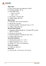
Page 13: ...e 4 X Internal reference clock 19 66 MHz X Position counter range 134 217 728 to 134 217 727 28 bit X Command counter setting range 134 217 728 to 134 217 728 28 bit X Pulse rate setting range 1 65 535 16 bit X Pulse rate multiplier setting range 0 1 100 Pulse Output X Line driver output X Max Speed 6 55 Mhz X Output Voltage Z Logic H 2 5V min Z Logic L 0 5V max X Isolated voltage 500 Vrms Encoder...

Page 14: ...ent 4 mA max X Switching capability 10 KHz 24V load 4 7 K X Isolated voltage 500 Vrms General Purpose Output X Output type NPN sinking type for N module PNP sourcing type for P module X Sink Current 90 mA max X Switching capability 2 KHz 24V load 300 X Isolated voltage 500 Vrms General Specifications X Operating Temperature 0 C 60 C X Storage Temperature 20 C 80 C X Humidity 0 90 non condensing Po...

Page 15: ...K website for latest update This module supports DOS Windows 98 NT 2000 XP For other OS please contact the local vendors Motion Creator on LinkMaster Utility This Windows based utility is used to setup cards motors and systems It can also aid in debugging hardware and software prob lems It allows users to set I O logic parameters to be loaded in their own program This product is also bundled with ...

Page 16: ...6 Introduction ...

Page 17: ...r 3 and their operation chapter 4 X Understanding the connector pin assignments the remain ing sections and wiring the connections 2 1 Package Contents In addition to this User s Guide the package also includes the fol lowing items X HSL 4XMO advanced 4 Axis Servo Stepper Motion Con trol Card X ADLINK All in one Compact Disc If any of these items are missing or damaged contact the dealer from whom...

Page 18: ...N2 Digital Input Common and Emergency Input Pin X HS1 2 HSL Communication Signal Connector RJ45 X HS3 HSL Communication Signal Connector WAGO X CM1 4 Servo Interface Signal Connector X IOIF1 4 Mechanical I O and GPIO Signal Connector X S1 Slave ID Switch X JP1 Communication Speed Selection Jumper X JP2 3 Full Duplex Half Duplex Selection Jumper ...

Page 19: ...n Name Description ICOM Mechanical Input and General Input Common EMG Emergency Stop Input Table 2 2 CN2 Pin Assignments Emergency Input and General Input Common PIN NO PIN OUT PIN 1 NC PIN 2 NC PIN 3 TXD PIN 4 RXD PIN 5 RXD PIN 6 TXD PIN 7 NC PIN 8 NC Table 2 3 HS1 HS2 Pin Assignments HSL Communication Signal RJ 45 HS3 Pin Name Description FG Shielding ground T TXD T TXD R RXD R RXD Table 2 4 HS3...

Page 20: ...6 ERC Deviation counter clear output signal 17 EGND External power ground 18 E24V External power supply 24V 19 RDY Ready input signal 20 ALM Alarm input signal Table 2 5 CM1 CM4 Pin Assignments Servo Interface Pin No Pin Name Description 1 E24V External power supply 24V 2 MEL End limit input signal 3 ORG Origin input signal 4 PEL End limit input signal 5 LTC SD Ramp down position latch input signa...

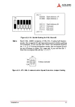
Page 21: ...he occupied ID will be continuously from this setting For example if you set the ID 1 then the occupied IDs will be 1 2 3 4 If using full duplex mode the occupied ID will be two ID steps in order For example if you set the ID 1 then the occupied IDs will be 1 3 5 7 Figure 2 3 JP1 HSL Communication Speed Selection Jumper Setting ...

Page 22: ...12 Installation Figure 2 4 P2 3 HSL Full Duplex Half Duplex Jumper Setting Figure 2 5 JP4 HSL Termination Resistor Jumper Setting ...

Page 23: ... DIR X Section 3 2 Encoder Feedback Signals EA EB and EZ X Section 3 3 Origin Signal ORG X Section 3 4 End Limit Signals PEL and MEL X Section 3 5 Ramping down Position latch signals X Section 3 6 In position signals INP X Section 3 7 Alarm signal ALM X Section 3 8 Deviation counter clear signal ERC X Section 3 9 General purpose signals SVON X Section 3 10 General purpose signal RDY X Section 3 11...

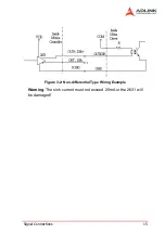
Page 24: ... also be programmed as CW and CCW signal pairs In this section the electrical characteristics of the OUT and DIR signals are detailed Each signal consists of a pair of differential signals For example OUT2 consists of OUT2 and OUT2 signals The following wiring diagram is for OUT and DIR signals on the 4 axes Figure 3 1 OUT and DIR Signals on the 4 Axes Non differential type wiring example Choose o...

Page 25: ...Signal Connections 15 Figure 3 2 Non differential Type Wiring Example Warning The sink current must not exceed 20mA or the 2631 will be damaged ...

Page 26: ...served when connecting to the encoder feedback or motor driver feedback as not to over drive the source The differential signal pairs are converted to digital signals EA EB and EZ then feed to the PCL6045 ASIC R 220ohm Below are examples of connecting the input signals with an exter nal circuit The input circuit can be connected to an encoder or motor driver if it is equipped with 1 a differential...

Page 27: ...r source The connection between the HSL 4XMO encoder and the power supply is shown in the diagram below Note that an external current limiting resistor R is necessary to protect the HSL 4XMO input circuit The following table lists the suggested resistor values according to the encoder power supply X If 6mA max Encoder Power VDD External Resistor R 5V 0Ω None 12V 1 8kΩ 24V 4 3kΩ Table 3 1 Encoder P...

Page 28: ...ut circuit of the ORG signals is shown below Usually a limit switch is used to indicate the origin on one axis The specifi cations of the limit switch should have contact capacity of 24V 6mA minimum An internal filter circuit is used to filter out any high frequency spikes which may cause errors in the operation Figure 3 6 Origin Signal ORG When the motion controller is operated in the home return...

Page 29: ...her A type normal open contact or B type normal closed contact switches can be used The type of switch can be config ured by software For more details on EL operation refer to sec tion 4 8 Figure 3 7 End Limit Signals PEL and MEL 3 5 Ramping down Position Latch There is a SD LTC signal for each of the 4 axes A circuit diagram is shown below Typically the limit switch is used to generate a slow dow...

Page 30: ... servo s posi tion indicates zero The input circuit of the INP signals is shown in the diagram below Figure 3 9 In position Signal INP The in position signal is usually generated by the servomotor driver and is ordinarily an open collector output signal An external circuit must provide at least 6mA current sink capabilities to drive the INP signal For more details of INP signal operations refer to...

Page 31: ...etails of ALM signal operations refer to section 4 7 Figure 3 10 Alarm Signal ALM 3 8 Deviation Counter Clear Signal ERC The deviation counter clear signal ERC is active in the following 4 situations 1 Home return is complete 2 End limit switch is active 3 An alarm signal stops OUT and DIR signals 4 An emergency stop command is issued by software operator The ERC signal is used to clear the deviat...

Page 32: ...rvomotor on control or gen eral purposed output signal The output circuit for the SVON sig nal is shown below Figure 3 12 General purpose Signal SVON 3 10 General purpose Signal RDY The RDY signals can be used as motor driver ready input or gen eral purpose input signals The input circuit of RDY signal is shown in the following diagram ...

Page 33: ...nals Figure 3 14 Position Compare Output CMP Note CMP trigger type can be set as normal low rising edge or normal high falling edge Default setting is normal high 3 12 Emergency Stop Input EMG There is emergency stop input pin for this module When EMG is active all the motion pulse output command will be rejected until the EMG is deactive A circuit diagram is shown in the diagram below The emergen...

Page 34: ...put EMG 3 13 General purpose Input HSL 4XMO has 4 opto isolated digital inputs for general purposed use The following wiring diagrams are of these signals Figure 3 16 General purpose Input 3 14 General purpose Output HSL 4XMO has 4 opto isolated digital outputs for general pur posed use The following wiring diagrams are of these signals ...

Page 35: ...nnections 25 NPN type general purpose Output available in N modules Figure 3 17 NPN Type General Purpose Output PNP type general purpose Output available in P modules Figure 3 18 PNP Type General Purpose Output ...

Page 36: ...26 Signal Connections ...

Page 37: ...mote modules Then the remote modules will interpret those packets and execute the commands correctly Before launching the packet all the commands issued by users are written into the dual port RAM and transferred on HSL net work Consequently the dual port RAM is the bridge between HSL master controller and host PC The accessing time of dual port RAM for one packet is about 600ns It is quiet fast o...

Page 38: ...p For example if the module start ID 1 then it occupies ID 1 2 3 4 If having two slave modules we suggest that the second ID can be set at 5 Then the seoncd module occu pies ID 5 6 7 8 Host command on PC is transferring via HSL protocol The base time for one ID at 6Mhz data transder rate is 30us The more IDs exist in HSL system the more scan time is needed For example one HSL 4XMO module occupies ...

Page 39: ...nd Timing The base scan time table is as follows N is the range of total IDs Half Duplex Full Duplex Maximum Length 3M 120 us x N 60 us x N 400 meters 6M 60 us x N 30 us x N 200 meters 12M 30 us x N 15 us x N 100 meters Table 4 1 Base Scan Times ...

Page 40: ...ommand data download ing command point table command and script program downloading command The command dispatching task is executed every HSL scan cycle It is real time While the DSP in idling the other tasks such as position compare point table motion script motion special speed profile control and data monitoring are running at lower priority than command dispatching The timing block diagram as...

Page 41: ...e OUT DIR and 2 dual pulse output mode CW CCW type pulse output The software function HSL_M_set_pls_outmode is used to program the pulse com mand mode The modes vs signal type of OUT and DIR pins are listed in the table below The interface characteristics of these signals can be differential line driver or open collector output Please refer to section 3 1 for the jumper setting for different signa...

Page 42: ...put Mode OUT DIR Mode Dual Pulse Output Mode CW CCW Mode In this mode the waveform of the OUT and DIR pins represent CW clockwise and CCW counter clockwise pulse output respectively Pulses output from the CW pin makes the motor move in positive direction whereas pulse output from the CCW pin makes the motor move in negative direction The following diagram shows the output waveform of positive comm...

Page 43: ...ction is use for acceleration according to the S curve The pulse output rate is kept at maxi mum velocity until another velocity command is set or a stop com mand is issued The HSL_M_v_change is used to change the speed during an operation Before this function is applied be sure to call HSL_M_fix_speed_range Please refer to section 4 6 for more detail explanation The HSL_M_sd_stop function is used...

Page 44: ...speed_range Trapezoidal Motion This mode is used to move a singe axis motor to a specified posi tion or distance with a trapezoidal velocity profile The single axis is controlled from point to point An absolute or relative motion can be performed In absolute mode the target position is assigned In relative mode the target displacement is assigned In both cases the acceleration and deceleration can...

Page 45: ...nal feedback pulse input must be appropri ately set by the HSL_M_set_move_ratio function In the HSL_M_start_tr_move function the relative displacement must be given in units of pulses Unsymmetrical trapezoidal veloc ity profile Tacc is not equal Tdec can be specified with both HSL_M_start_ta_move and HSL_M_start_tr_move functions The StrVel and MaxVel parameters are given in units of pulses per se...

Page 46: ...0 60 2000 4 480000 PPS Multiplying by 4 is necessary because there are four states per AB phase See Figures in Section 4 4 Usually the axes need to set the move ratio if their mechanical resolution is different from the resolution of command pulse For example if an incremental encoder is mounted on the working table to measure the actual position of moving part A servomotor is used to drive the mo...

Page 47: ...ion_done HSL_M_set_feedback_src HSL_M_set_move_ratio S curve Profile Motion This mode is used to move a single axis motor to a specified posi tion or distance with a S curve velocity profile S curve accelera tion profiles are useful for both stepper and servomotors The smooth transitions between the start of the acceleration ramp and transition to constant velocity produce less wear and tear than ...

Page 48: ... S curve region during acceleration in units of PPS X VSdec S curve region during deceleration in units of PPS Figure 4 9 S curve Profile Motion Normally the accel decel period consists of three regions two VSacc VSdec curves and one linear During VSacc VSdec the jerk second derivative of velocity is constant and during the lin ear region the acceleration first derivative of velocity is constant I...

Page 49: ...lways pro duce smooth motion If the time for acceleration parameters com bined with the final position don t allow an axis to reach the maximum velocity i e the moving distance is too small to reach MaxVel then the maximum velocity is automatically lowered see the following figure The rule is to lower the value of MaxVel and the Tacc Tdec VSacc VSdec automatically and keep StrVel acceleration and ...

Page 50: ...xes for linear interpolation on a single card at the same time You can however use one 2 axis linear and one 2 axis circular interpolation at the same time If you want to stop an interpolation group the function HSL_M_sd_stop or HSL_M_emg_stop can be used 2 Axes Linear Interpolation As in the diagram below 2 axis linear interpolation means to move the XY position or any 2 of the 4 axis from P0 to ...

Page 51: ... 5000 0 0 1 0 2 will cause the XY axes axes 0 1 of Card 0 to perform a linear interpolation movement in which X 30000 pulses Y 40000 pulses Start vector speed 1000pps X speed 600pps Y speed 800pps Max vector speed 5000pps X speed 3000pps Y speed 4000pps Acceleration time 0 1sec Deceleration time 0 2sec There are two groups of functions that provide 2 axis linear inter polation The first group divi...

Page 52: ...t s r and a after HSL_M_start mean X t Trapezoidal profile X s S Curve profile X r Relative motion X a Absolute motion 3 Axis Linear Interpolation Any 3 of the 4 axes of the HSL 4XMO may perform 3 axis linear interpolation As shown the figure below 3 axis linear interpolation means to move the XYZ if axes 0 1 2 are selected and assigned to be X Y Z respectively position from P0 to P1 starting and ...

Page 53: ... 3000 pulse Start vector speed 100pps X speed 100 26 7pps Y speed 2 100 53 3pps Z speed 3 100 80 1pps Max vector speed 5000pps X speed 5000 1336pps Y speed 2 5000 2672pps Z speed 3 5000 4008pps The following functions are used for 3 axis linear interpolation HSL_M_start_tr_line3 HSL_M_start_sr_line3 HSL_M_start_ta_line3 HSL_M_start_sa_line3 The characters t s r and a after HSL_M_start mean X t Tra...

Page 54: ...interpolation for 2 axes Any 2 of the 4 axes of the HSL 4XMO can perform circular interpo lation In the example below circular interpolation means XY if axes 0 1 are selected and assigned to be X Y respectively axes simultaneously start from initial point 0 0 and stop at end point 1800 600 The path between them is an arc and the Max Vel is the tangential speed Figure 4 13 Circular interpolation fo...

Page 55: ...he target axes are already assigned HSL_M_start_r_arc_xy HSL_M_start_r_ arc _zu HSL_M_start_a_ arc _xy HSL_M_start_a_ arc _zu The second group allows user to freely assign any targeted 2 axes HSL_M_start_r_arc2 HSL_M_start_a_arc2 Circular Interpolation with Acc dec Time In section 4 1 the circular interpolation functions do not support acceleration and deceleration parameters therefore they cannot...

Page 56: ...Acceleration Time The maximum velocity parameter of a motion function will eventu ally have a minimum acceleration value This means that there is a range for acceleration time over one velocity value Under this relationship to obtain a small acceleration time a higher maxi mum velocity value to match the smaller acceleration time is required Function HSL_M_fix_speed_range will provide such operati...

Page 57: ...put value will be the minimum and maximum val ues of the acceleration time For example if the original acceleration range for the command is HSL_M_start_tr_move AxisNo 5000 0 5000 0 001 0 0 01 then use the following function HSL_M_verify_speed 0 5000 minAccT maxAccT 5000 The value miniAccT will be 0 0267sec and maxAccT will be 873 587sec This minimum acceleration time does not meet the requirement...

Page 58: ...e of HSL_M_verify_speed is the minimum velocity of motion command it does not always equal to your start velocity setting In the above example it will be 3pps more than the 0pps setting To disable the fix speed function HSL_M_fix_speed_range use HSL_M_unfix_speed_range Minimize the use of the OverVelocity operation The more it is used the coarser the speed interval is Figure 4 16 Velocity and Acce...

Page 59: ...r completion of home move it is necessary to keep in mind that all related position information should be reset to be 0 The HSL 4XMO has 4 counters and 1 software maintained position recorder They are X Command position counter counts the number of pulse out puts X Feedback position counter counts the number of pulse inputs X Position error counter counts the error between command and feedback pul...

Page 60: ...et_pos The following figures show the various home modes and the reset points when the counter is cleared to 0 home_mode 0 ORG Slow down Stop X When SD Ramp down signal is inactive Figure 4 17 home_mode 0 home_mode 1 ORG Slow down Stop at end of ORG X When SD Ramp down signal is active ...

Page 61: ...Operation Theory 51 Figure 4 18 home_mode 1 home_mode 3 ORG EZ Slow down Stop Figure 4 19 home_mode 3 ...

Page 62: ...52 Operation Theory home_mode 4 ORG Slow down Go back at FA speed EZ Stop Figure 4 20 home_mode 4 home_mode 5 ORG Slow down Go back Accelerate to MaxVel EZ Slow down Stop ...

Page 63: ...Operation Theory 53 Figure 4 21 home_mode 5 home_mode 6 EL only Figure 4 22 home_mode 6 home_mode 7 EL Go back Stop on EZ signal Figure 4 23 home_mode 7 ...

Page 64: ...54 Operation Theory home_mode 8 EL Go back Accelerate to MaxVel EZ Slow down Stop Figure 4 24 home_mode 8 home_mode 9 ORG Slow down Go back Stop at beginning edge of ORG Figure 4 25 home_mode 9 ...

Page 65: ... home_mode 10 ORG EZ Slow down Go back Stop at beginning edge of EZ Figure 4 26 home_mode 10 home_mode 11 ORG Slow down Go back backward Accelerate to MaxVel EZ Slow down Go back again forward Stop at beginning edge of EZ ...

Page 66: ...56 Operation Theory Figure 4 27 home_mode 11 home_mode 12 EL Stop Go back backward Accel erate to MaxVel EZ Slow down Go back again for ward Stop at beginning edge of EZ Figure 4 28 home_mode 12 ...

Page 67: ...Operation Theory 57 Home Search Example Home mode 1 Figure 4 29 Home Search Example ...

Page 68: ...moving 3 ORG touches slow down 4 Escape from ORG according to ORG offset 5 Start searching again 6 ORG touches slow down then using searching speed to escape ORG 7 After escape ORG search ORG with search speed again X Relative Functions HSL_M_set_home_config HSL_M_home_move HSL_M_home_search ...

Page 69: ...with a pulse train input has a deviation position error counter to detect the deviations between the input pulse command and feedback counter The driver controls the motion of the servomotor to minimize the deviation until it becomes 0 Theoretically the servomotor operates with some time delay from the command pulses Likewise when the pulse gener ator stops outputting pulses the servomotor does no...

Page 70: ...ignal output from the servo driver The signal immediately stops the HSL 4XMO from generat ing any further pulses or stops it after deceleration If the ALM sig nal is in the ON status at the start of an operation the HSL 4XMO will generate the INT signal and thus not generate any command pulses The ALM signal may be a pulse signal with a minimum time width of 5 microseconds Setting the parameters a...

Page 71: ...omotor by resetting the deviation counter to zero The ERC signal is outputted as a one shot signal The pulse width is of time length defined by the function call HSL_M_set_erc The ERC signal will automatically be generated when the EL and ALM signal are turned on and the servomotor is stopped immedi ately X Relative Functions HSL_M_set_erc SVON and RDY All axes of the HSL 4XMO are equipped with SV...

Page 72: ...SD Slow Down or Posi tion Latch LTC This input pin is inside connected to both slow down function and latch function Users can control the slow down function to be active or not But the latch function is always turned on without any problem Care must be taken with the logic attributes of the signal not being used The slow down signals are used to force the output pulse OUT and DIR to decelerate to...

Page 73: ...direc tion MEL signal indicates the end limit in negative minus direc tion When the output pulse signals OUT and DIR is towards the positive direction the pulse train will be immediately stopped when the PEL signal is asserted where the MEL signal is meaningless and vise versa When the PEL is asserted only a negative minus direction output pulse can be generated when moving the motor in a negative...

Page 74: ...en command and feedback pulse numbers X General purpose counter The source can be configured as pulse output feedback pulse manual pulse or CLK 2 Also the target position recorder a software maintained position recorder is discussed Command Position Counter The command position counter is a 28 bit binary up down counter its input source is the output pulse from the HSL 4XMO thus it provides accura...

Page 75: ...on its rotating direction These input modes can be selected using the HSL_M_set_pls_iptmode function In cases where the application has not implemented an encoder it is possible to set the feedback counter source to generate the out put pulses just as with the command counter Thus the feedback counter and the command counter will have the same value To enable the counters to count the number of pu...

Page 76: ...nput logic polarity of the EZ signals is program mable using software function HSL_M_set_home_config The EZ signals status of the four axes can be monitored by get_io_status The feedback position counter will be automatically cleared to 0 after a home move is complete Besides setting a position with the function call HSL_M_set_position it can also be executed at any time to set a new position valu...

Page 77: ...ter To reset the position error counter use the function call HSL_M_reset_error_counter The position error counter will automatically clear to 0 after home move is complete X Relative Functions HSL_M_get_error_counter HSL_M_reset_error_counter General Purpose Counter The general purpose counter is very versatile It can be any of the following 1 Pulse output as a command position counter 2 Pulse in...

Page 78: ...M_reset_target_pos Counter Description Counter Source Function Function Description Command Counts the number of output pulses Pulse output HSL_M_set_command Set a new value for com mand position HSL_M_get_command Read current command position Feedback Counts the number of input pulses EA EB or Pulse output HSL_M_set_pls_iptmode Select the input modes of EA EB HSL_M_set_feedback_src Set the counte...

Page 79: ...O modules in one HSL set This means up to 63 motors max imum axes can be connected When multiple modules are used the order of axes number is from low to high and each module takes four axis number Table 4 5 Multiple HSL 4XMO Operations Example To accelerate CM3 of module 2 from 0 to 10000pps in 0 5sec for Constant Velocity Mode operation the axis number is 6 and the code for the program will be H...

Page 80: ...e Fly Figure 4 31 Change Speed on the Fly The change speed on the fly function is applicable on single axis motion only Both velocity mode motion and position mode motion are acceptable The graph above shows the basic operating the ory The following functions are related to changing speed on the fly HSL_M_v_change change the MaxVel on the fly HSL_M_cmp_v_change change velocity when the general com...

Page 81: ...section 4 4 4 for more details about the general comparator The last 4 functions are relatively easy to understand and use So the discussion below will be focused on HSL_M_v_change Theory behind HSL_M_v_change The HSL_M_v_change function is used to change MaxVel on the fly In a normal motion operation the axis starts at StrVel speed accelerates to MaxVel and then maintains MaxVel until it enters t...

Page 82: ...ing pulses to reach the new velocity else the HSL_M_v_change will return an error and the velocity remains unchanged Example A trapezoidal relative motion is applied HSL_M_start_tr_move 0 10000 0 1000 0 1 0 1 It cause axis 0 to move for 10000 pulses and the maximum veloc ity is 1000 PPS At 5000 pulses HSL_M_v_change 0 NewVel Tacc is applied ...

Page 83: ...ity where HSL_M_v_change can not be exceeded Figure 4 33 Velocity Suggestions A 2 During the acceleration or deceleration period using HSL_M_v_change is not suggested although it does work in most cases the acceleration and deceleration time is not guaranteed NewVel PPS Tacc Sec Necessary remaining pulses OK Error Acceleration Deceleration Total 5000 0 1 300 313 613 OK 5000 1 3000 3125 6125 Error ...

Page 84: ...1 is touched Change to 50000pps if Sensor 2 is touched Change to 100000pps if Sensor 3 is touched Then the code for this application and the resulting velocity profiles are shown below Figure 4 35 Velocity Example include pci_HSL 4XMO h HSL_M_fix_speed_range axis 100000 0 HSL_M_start_ta_move axis 200000 0 1000 10000 0 02 0 01 while HSL_M_motion_done axis Get sensor s information from another I O c...

Page 85: ...Sensor1 Low Sensor2 Low Sensor3 High HSL_M_v_change axis 100000 0 02 The information of the three sensors is acquired from another I O card and the resulting velocity profile from experiment is shown below Figure 4 36 Velocity Profile Example X Relative Functions HSL_M_v_change HSL_M_sd_stop HSL_M_emg_stop HSL_M_fix_speed_range HSL_M_unfix_speed_range HSL_M_get_currebt_speed ...

Page 86: ...o the HSL_M_start_ta_move and HSL_M_start_sa_move functions only It is used to change the target position defined originally by these two functions After changing position the axis will move to the new target position and totally disregard the original position If the new position is in the passed path it will cause the axis to decelerate and eventually stop then reverse as shown in the chart The ...

Page 87: ...eration period is not allowed 3 There must be enough distance between the new target position and current position where HSL_M_p_change is executed because the HSL 4XMO needs enough space to finish deceleration Example A trapezoidal absolute motion is applied HSL_M_start_ta_move 0 10000 0 1000 0 5 1 It cause axis 0 to move to pulse 10000 position with a maximum velocity of 1000 PPS The necessary n...

Page 88: ... comparator has its unique functionality Below is a table for com parison NewPos CurrentPos OK Error Note 5000 4000 OK 5000 4501 Error 5000 5000 Error 5000 5499 Error 5000 6000 OK Go back 5000 9499 OK Go back 5000 9500 Error 5000 9999 Error Table 4 7 HSL_M_p_change Constraints Compare Source Description Function Related Comparator 1 Command posi tion counter Soft Limit Refer to section 4 9 HSL_M_s...

Page 89: ...0 and 1 can do a position comparison The position comparison function triggers a pulse output via the CMP when the comparing condition comes into existence The comparing condition consists of 2 parts the first is the value to be compared and the second is the comparing mode Comparing mode can be or The easiest way to use the position comparison function is to call the function HSL_M_set_trigger_co...

Page 90: ...lds a comparison list using start and end points and constant intervals The second function builds on an arbitrary comparison table data array The third function is a source comparing selection function Users can check current val ues used for comparison using the function HSL_M_check_compare_data Example Using the continuous position comparison function Figure 4 39 Continuously Comparison with Tr...

Page 91: ...data HSL_M_check_compare_data 0 5 CurrentData Users can use this function to check if auto trigger is running The Value block in this figure is the position where the compari son occurs and where the data can be checked by using HSL_M_check_compare_data Note that at the final compared point will still load an After final point into the Value block Fill a dummy point into the comparison table array...

Page 92: ...klash_comp is used to set the pulse number In order to minimize vibration when a motor stops the HSL 4XMO can output a single pulse for a negative direction and then single pulse for a positive direction right after completion of a command movement Refer to the timing chart below the HSL_M_suppress_vibration function is used to set T1 T2 Figure 4 40 Vibration Suppression X Relative Functions HSL_M...

Page 93: ...efer to 4 4 In cases where the mov ing ratio is not equal to 1 it is necessary to manually calcu late its corresponding command position where the soft limit would be when using HSL_M_set_softlimit X Relative Functions HSL_M_set_softlimit HSL_M_enable_softlimit HSL_M_diable_softlimit 4 15 Point Table Management For rapid and multiple point to point motion application it would take much more time t...

Page 94: ...use the module plays as a standalone system and execute the motion commands by itself Windows context switching would not interrupt the module Con sequently it has a better timing performance than non standalone system The motion script supports standard G code and many tradi tional users are familiar with it Users can use any text editor pro gram to define their motion sequence and download it in...

Page 95: ...n path LinkMaster To execute the program double click on the execut able file or use Start Program Files HSL LinkMaster 5 2 About Motion Creator in LinkMaster Before Running Motion Creator the following issues should be kept in mind 1 Motion Creator is available only for Windows system with a screen resolution higher than 800x600 It cannot be run under DOS 2 Motion Creator allows users to save set...

Page 96: ...86 Motion Creator in LinkMaster developed program This function is available in a DOS environment as well Figure 5 1 HSL Master Utility ...

Page 97: ...Menu The main menu appears after running Motion Creator It is used to Figure 5 2 Main Menu X Select Axis X Go to Operate menus X Go to Interface I O configuration menus X Go to Config Pulse I O menus X Show Module information X Show Software information X Exit Motion Creator ...

Page 98: ...88 Motion Creator in LinkMaster Interface I O Configuration Menu In this menu users can configure EL ORG EZ ERC ALM INP SD and LTC Figure 5 3 Interface I O Configuration Menu ...

Page 99: ...he logic of the ORG signal The related function call is HSL_M_set_home_config 5 EZ Logic Select the logic of the EZ signal The related function call is HSL_M_set_home_config 6 SD Configuration Configure the SD signal The related function call is HSL_M_set_sd 7 LTC Logic Select the logic of the LTC signal The related function call is HSL_M_set_ltc_logic 8 Buttons X Next Axis Change operating axis X...

Page 100: ...Input Sets the configurations of the Pulse input signal EA EB The related function calls are HSL_M_set_pls_iptmode HSL_M_set_feedback_src 3 Buttons X Next Axis Change operating axis X Save Config Save current configuration to HSL 4XMO ini X Operate Go to the operation menu refer to section 5 3 4 X Config Pulse Go to the Pulse IO Configuration menu refer to section 5 3 3 X Back Return to the main m...

Page 101: ...Motion Creator in LinkMaster 91 Operation Menu In this menu users can change the settings a selected axis including velocity mode motion preset relative absolute motion manual pulse move and home return ...

Page 102: ...rget_pos 2 Position Reset clicking this button will set all positioning counters to a specified value The related functions are HSL_M_set_position HSL_M_set_command HSL_M_reset_error_counter HSL_M_reset_target_pos 3 Motion Status Displays the returned value of the HSL_M_motion_done function The related function is HSL_M_motion_done 4 Velocity The absolute value of velocity in units of PPS The rela...

Page 103: ..._move X Relative Mode Distance will be used as relative displace ment for motion The related function is HSL_M_start_tr_move HSL_M_start_sr_move X Cont Move Velocity motion mode The related function is HSL_M_tv_move HSL_M_start_sv_move X Home Mode Home return motion Clicking this button will invoke the home move configuration window The related function is HSL_M_set_home_config If the check box AT...

Page 104: ...if the ERC signal will be sent when home move completes X EZ Count Set the EZ count number which is effective on certain home return modes X Mode Select the home return mode There are 13 modes available X Home Mode figure The figure shown explains the actions of the individual home modes ...

Page 105: ...Set the start velocity of motion in units of PPS In Absolute Mode or Relative Mode only the value is effective For example 100 0 is the same as 100 0 In Cont Move both the value and sign are effective 100 0 means 100 0 in the minus direction X Maximum Velocity Set the maximum velocity of motion in units of PPS In Absolute Mode or Relative Mode only the value is effective For example 5000 0 is the ...

Page 106: ... Clicking this button will cause the HSL 4XMO start to outlet pulses according to previous setting Z In Absolute Mode it causes the axis to move to posi tion Z In Relative Mode it causes the axis to move back wards Z In Cont Move it causes the axis to start to move according to the velocity setting but in the opposite direction 15 Change Position On The Fly Button When this button is enabled users...

Page 107: ...ht Off indicates inactive The related function is HSL_M_get_io_status 19 Buttons X Next Axis Change operating axis X Save Config Save current configuration to HSL 4XMO ini X Config Pulse Go to the Pulse IO Configuration menu refer to section 5 3 X Config Interface I O Go to the Interface I O Configuration menu refer to section 5 3 X Back Return to the main menu ...

Page 108: ...98 Motion Creator in LinkMaster ...

Page 109: ...U32 command None 4 Get U16 command None 5 Get U32 command None 6 One axis motion 6 Delivering Times 7 Two axis motion 7 Delivering Times 8 Short term motion 2 Delivering Times Table 6 1 Commmand Executuion Classifications Command Type Time ms Example One module ID 1 3 5 7 Four modules ID 1 16 Eight modules ID 1 32 1 0 413 0 500 1 000 HSL_M_set_pls_outmode 2 0 429 0 501 1 000 HSL_M_set_home_config ...

Page 110: ... us Theoretical command time is recommend as follows Z If the module is smaller than 4 the time is roughly 0 5 ms Z If the quantity of the modules is odd the time is about 0 5 Num 1 4 2 0 24 ms Z If the quantity of the modules is even the time is about 0 5 Num 4 2 0 24 ms ...

Page 111: ...manufactured by ADLINK will be covered by the original manufactur ers warranty X For products containing storage devices hard drives flash cards etc please back up your data before send ing them for repair ADLINK is not responsible for loss of data X Please ensure the use of properly licensed software with our systems ADLINK does not condone the use of pirated software and will not service systems...

Page 112: ... cals X Damage caused by leakage of battery fluid during or after change of batteries by customer user X Damage from improper repair by unauthorized techni cians X Products with altered and or damaged serial numbers are not entitled to our service X Other categories not protected under our warranty 4 Customers are responsible for shipping costs to transport damaged products to our company or sales...

Reviews: