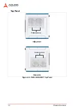
14
Chassis Overview
2.2
Backplane Features
Inter-operability with CompactPCI
With backplanes that are compliant with PXI Specification Rev.
2.2, the PXIS-2508 and PXIS-2558T are designed to support both
standard PXI and CompactPCI modules.
The signals on the backplane’s P1 connector meet the require-
ments of CompactPCI specifications for both peripheral and sys-
tem modules. The PXI-specific signals located on P2 are reserved
or unused in CompactPCI 64-bit specifications. This allows periph-
eral modules with CompactPCI 64-bit specifications to function in
both PXIS-2508 and PXIS-2558T.
NOTE
CompactPCI peripheral modules which operate with rear
I/O modules may not work in PXIS-2508/2558T due to
the conflict between rear I/O signals and PXI-specific sig-
nals on J2.
System Controller Slot
Slot 1 is designated as the system controller slot as defined by PXI
specifications. The PXIS-2508/PXIS-2558T can accommodate a
PXI system controller with up to 3-slot width. As defined in PXI
specifications, the system controller slot allows the controller to
expand to the left to prevent it from occupying the peripheral slot
space.
Star Trigger Slot
Slot 2 is designated as the star trigger (ST) slot. This slot comes
with dedicated trigger lines between itself and peripheral slots 3 to
8. The star trigger functionality is intended to provide precise trig-
ger signals to the peripheral modules by installing a specific star
trigger controller modules in the ST slot. The star trigger slot can
be also used as a general peripheral slot if you will not use the star
trigger functionality.
Summary of Contents for 96864-1
Page 11: ......
Page 17: ...6 Introduction ...
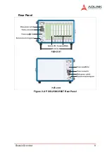
Page 20: ...Chassis Overview 9 Rear Panel Figure 2 2 PXIS 2508 2558T Rear Panel Foot stand ...
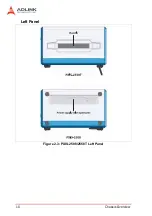
Page 21: ...10 Chassis Overview Left Panel Figure 2 3 PXIS 2508 2558T Left Panel ...
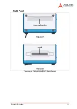
Page 22: ...Chassis Overview 11 Right Panel Figure 2 4 PXIS 2508 2558T Right Panel ...
Page 23: ...12 Chassis Overview Top Panel Figure 2 5 PXIS 2508 2558T Top Panel ...
Page 24: ...Chassis Overview 13 Base Panel Figure 2 6 PXIS 2508 2558T Base Panel ...
Page 31: ...20 Installation 5 Fasten the screw on the module front panel then con nect all devices ...
Page 41: ...30 Installation ...
Page 53: ...42 Remote Management ...


