


8
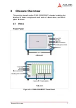
Chassis Overview
LED Indications
Alarm Reset Button
The alarm reset button enables you to stop the chassis alarm
during an error or critical system event. To stop the alarm,
press the alarm reset button.
LED
Status
On
Off
Blinking
Power (Blue)
DC voltages are
supplied
normally.
No DC power is
supplied.
• 5 V or 3.3 V exceeds
±7% range
• 12 V or -12 V exceeds
±12% range
Fan (Green)
Fans are
operating
normally.
The system is
off.
Any of the fans is
operating in a speed
lower than 500 RPM
Temp (Amber)
Chassis
temperature is
normal
The system is
off.
Chassis temperature
exceeds 50°C
Summary of Contents for 96864-1
Page 11: ......
Page 17: ...6 Introduction ...
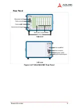
Page 20: ...Chassis Overview 9 Rear Panel Figure 2 2 PXIS 2508 2558T Rear Panel Foot stand ...
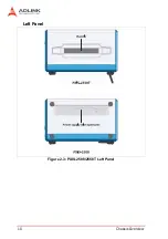
Page 21: ...10 Chassis Overview Left Panel Figure 2 3 PXIS 2508 2558T Left Panel ...
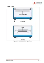
Page 22: ...Chassis Overview 11 Right Panel Figure 2 4 PXIS 2508 2558T Right Panel ...
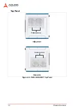
Page 23: ...12 Chassis Overview Top Panel Figure 2 5 PXIS 2508 2558T Top Panel ...
Page 24: ...Chassis Overview 13 Base Panel Figure 2 6 PXIS 2508 2558T Base Panel ...
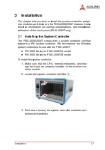
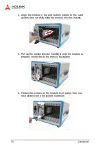
Page 31: ...20 Installation 5 Fasten the screw on the module front panel then con nect all devices ...
Page 41: ...30 Installation ...
Page 53: ...42 Remote Management ...