8
INST
ALLA
TION
CONFIGURA
TION
OPERA
TION
FUR
THER
INFORMA
TION
INDEX
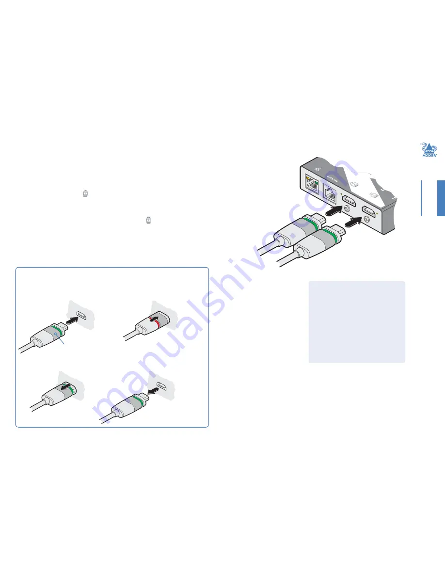
HDMI connections
The AdderLink DV104T transmitter has two input sockets that can be connected to
HDMI ports located on the same or different host computers, as required. A single
HDMI 1.5 meter connection lead is supplied with the transmitter unit.
To connect the HDMI input port(s)
1 Use the supplied HDMI cable to link the output port of the host computer to the
primary HDMI input port ( ) of the transmitter unit. See the section below for
details about the locking connectors used on Adder HDMI leads.
2 If a second link is required, use a high quality HDMI cable (of no more than 2 meters
in length - Adder part number: VSCD12) to join another port on the same (or
different) computer to the secondary HDMI input port ( ) of the transmitter unit.
Primary
HDMI
video/audio
input
Secondary
HDMI
video/audio
input
Indicators
The HDMI input ports each have an
adjacent recessed
orange indicator
to
provide useful configuration feedback, as
follows:
•
On
- The port is active and routed
(using the AdderLink POD Manager) to
a receiver.
•
Flashing
- The port is active but is
not currently routed to a receiver. For
instance, if it is yet to be configured or is
set up as a backup/standby input.
Using Adder locking HDMI connectors
The HDMI cables supplied by Adder feature a locking mechanism to prevent accidental
disconnections. Please follow the procedures below when inserting and removing them:
Insertion
2
Push the locking
collar forward
(to show red).
1
With the locking collar
pulled back (to show
green), insert the
connector.
Locking collar
Removal
1
Pull the locking
collar back (to
show green).
2
Gently pull
the connector
to disengage
it from the
socket.
IMPORTANT: Do not attempt to insert or remove
the connector while the red band is shown.


