background image

INSTRUCTION MANUAL

This device complies with Part 15 of the FCC Rules. Op-
eration is subject to the condition that this device does not 
cause harmful interference.

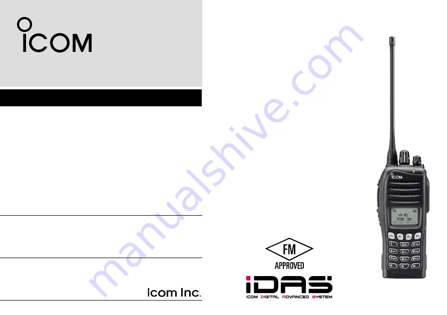
The photo shows the 
UHF transceiver.

iF4161DT

UHF TRANSCEIVER

iF4161DS

iF3161DT

VHF TRANSCEIVER

iF3161DS

Summary of Contents for IC-F3161DS

Page 1: ...omplies with Part 15 of the FCC Rules Op eration is subject to the condition that this device does not cause harmful interference The photo shows the UHF transceiver iF4161DT UHF TRANSCEIVER iF4161DS iF3161DT VHF TRANSCEIVER iF3161DS ...

Page 2: ...l property rights including patent rights copyrights and trade secrets of Digital Voice Systems Inc This voice coding Technology is licensed solely for use within this Communications Equipment The user of this Technology is explicitly prohibited from attempting to ex tract remove decompile reverse engineer or disassemble the Object Code or in any other way convert the Object Code into a human read...

Page 3: ...ers FM ap proval CAUTION Changes or modifications to this transceiver not expressly approved by Icom Inc could void your author ity to operate this transceiver under FCC regulations DO NOT push PTT when not actually desiring to trans mit DO NOT use or place the transceiver in direct sunlight or in areas with temperatures below 4 F 20 C or above 104 F 40 C The basic operations transmission and rece...

Page 4: ...e marking on the label The approval rating for these models are Intrinsically safe Class I II III Division 1 Groups D E F G Nonincendive Class I Division 2 Groups A B C D WARNING NEVER charge the BP 232FM with with out the transceiver in an explosive atmosphere The optional battery chargers are not approved as Intrinsically Safe When the transceiver is used in a hazardous area the BP 232FM MUST be...

Page 5: ...le function keys 6 3 BASIC OPERATION 11 18 Turning power ON 11 Channel selection 11 Call procedure 13 Receiving and transmitting 13 User set mode 16 Scrambler function 16 Stun function 16 Emergency transmission 17 Automatic Key Lock function 18 Priority A channel selection 18 4 BATTERY CHARGING 19 23 Caution 19 Optional battery chargers 21 5 SWIVEL BELT CLIP 24 25 MB 93 contents 24 To attach 24 To...

Page 6: ...ble antenna This illustration is for the UHF type Accessory attachments D Flexible antenna Connect the supplied flexible antenna to the antenna connector CAUTION NEVER carry the transceiver by holding only the antenna DO NOT connect the antenna other than listed on page 28 Transmitting without an antenna may damage the transceiver ...

Page 7: ...emove or attach the battery pack when the trans ceiver is wet or soiled This may result water or dust get ting into the transceiver battery pack and may result in the transceiver being damaged q w Battery release button Battery pack NOTE Keep the battery pack terminals clean It s a good idea to occasionally clean them D Belt clip To attach the belt clip q Remove the battery pack if it is attached ...

Page 8: ...Connector cover CAUTION Attach the connector cover when the optional equipment is not used Otherwise the terminals of the multi connec tor may be shorted by metal object etc and this could damage the transceiver To detach the connector cover q Remove the screw using a phillips screwdriver w Detach the connector cover for the optional equipment connector q w ...

Page 9: ...ammed by your dealer p 6 t PTT SWITCH PTT Push and hold to transmit release to receive y DEALER PROGRAMMABLE KEYS Side2 Side3 Desired function can be programmed independently by your dealer p 6 u 10 KEYPAD Depending on version The keypad allows you to enter digits to Select memory channels Select tone channels Select DTMF codes during transmit Set TX codes Start up with the password i DEALER PROGR...

Page 10: ... power ON OFF and adjusts the audio level Function display SET CALA TXCU TXC q t i u y r e w o 0 q SIGNAL STRENGTH INDICATOR Indicates relative signal strength level w LOW POWER INDICATOR Appears when low output power is selected e AUDIBLE INDICATOR Appears when the channel is in the audible unmute condition Appears when the matched signal is received r COMPANDER INDICATOR Appears when the compand...

Page 11: ... mode 0 KEY INDICATOR Indicate the programmed function of the front panel keys P0 P1 P2 and P3 Programmable function keys The following functions can be assigned to EMR Side1 Side2 Side3 P0 P1 P2 and P3 programmable function keys Consult your Icom dealer or system operator for details con cerning your transceivers programming If the programmable function names are bracketed in the fol lowing expla...

Page 12: ...eriod has passed Push and hold this key for 1 sec to indicate the scan list then push CH Up or CH Down to select the desired list SCAN ADD DEL TAG KEY SCAD Push to add channel to or delete it from the current scan group 1 Push to indicate the scan group then push CH Up or CH Down to select the desired group 2 Push to add or delete the channel to from the selected scan group 3 Push and hold for 1 s...

Page 13: ...er and OPT 1 2 3 Push and hold for 1 sec again to turn the lock function OFF LONE WORKER KEY LONE Push to turn the Lone Worker function ON or OFF If the Lone Worker function is activated the Emergency function is automatically turned ON after the specified time period has passed with no operation is performed HIGH LOW KEY H L Push to select the transmit output power temporarily or per manently dep...

Page 14: ...r dealer which call is assigned to each key EMERGENCY KEY EMR Push and hold to transmit the emergency call The emergency call transmits with beeps the display does not change The transceiver can transmit the emergency call silently or with the display changes depending on the pre setting Ask your dealer for details If you want to cancel the emergency call push and hold the key again before transmi...

Page 15: ... ON and OFF COMPANDER KEY COMP Push to toggle the compander function ON and OFF The compander function reduces noise components from the transmitting audio to provide clear communication USER SET MODE KEY SET Push and hold for 1 sec to enter user set mode During user set mode push this key to select an item that is enabled by your dealer and change the value or condition using push CH Up CH Down P...

Page 16: ...utting 6 digits the input code number may be incorrect Turn the power off and start over in this case Channel selection Several types of channel selections are available Methods may differ according to your system set up NON ZONE TYPE To select the desired operating channel Push CH Up or CH Down Rotate ROTARY SELECTOR Up to pre programmed 16 channels can be selected Push one of MR CH 1 to MR CH 4 ...

Page 17: ...he transceiver automatically starts scanning Scanning stops when receiving a call Depending on the pre setting When Rotary selector selects Operating channel CH Up CH Down are not available When Rotary selector selects Operating zone Zone Zone Up Zone Down are not available 1 2 3 4 5 6 7 8 9 10 11 12 13 14 15 16 ...

Page 18: ... 1 for accessory attachments Receiving q Rotate VOL to turn the power ON w Push CH Up or CH Down or rotate ROTARY SELEC TOR to select the conventional system channel in se quence Depending on the pre setting e When receiving a call adjust the audio output level to a comfortable listening level NOTE When a matched RX code signal is received audio from the microphone is automatically transmitted for...

Page 19: ...termined by the penalty timer D TX code channel selection If the transceiver has TX Code CH Select assigned to it the indication can be toggled between the operating channel number or name and TX code channel number or name When the TX code channel number or name is displayed CH Up or CH Down selects the TX code channel USING TX CODE CH SELECT KEY q Push TX Code CH Select a TX code channel number ...

Page 20: ...e CH Select to set Return to the stand by mode i Push Call to transmit USING TX CODE ENTER KEY q After pushing TX Code CH Select push CH Up or CH Down or push TX Code CH Up or TX Code CH Down to select the desired TX code channel w Push TX Code Enter to enter the TX code edit mode The digit to be edited blinks e Push TX Code Enter to select the desired digit to be ed ited r Push CH Up CH Down to s...

Page 21: ... Appears only when the external VOX unit is connected e Push and hold User Set Mode again to exit the User Set mode Scrambler function The voice scrambler function provides private communication between stations All versions have a built in frequency inver sion type scrambler Push Scrambler to toggle the scrambler function ON or OFF Scrambler indicator appears when the function is ON Stun function...

Page 22: ...ng the call If your transceiver is programmed for Silent operation you can transmit an Emergency call without the beep sounding and the LED indicator lighting IMPORTANT It is recommended to set an emergency channel individually to provide the certain emergency call operation Depending on the presetting Ask your dealer for details D NOTES Depending on the presetting the following functions are auto...

Page 23: ...tion is ON push and hold Lock for 1 sec to turn the function OFF When 0 is programmed this function is not available Priority A channel selection When one of the following operations is performed the trans ceiver selects the Priority A channel automatically Turning the power ON The Priority A channel is selected each time the trans ceiver power is turned ON Status call The Priority A channel is se...

Page 24: ...ratures above 40 C 104 F High tempera ture buildup in the battery such as could occur near fires or stoves inside a sun heated car or in direct sunlight may cause the battery to rupture or catch fire Excessive tem peratures may also degrade battery performance or shorten battery life R DANGER DO NOT expose the battery to rain snow seawater or any other liquids Never charge or use a wet battery If ...

Page 25: ... 35 C 4 F to 95 F within three months 20 C to 20 C 4 F to 68 F within a year D Charging caution R DANGER NEVER charge the battery pack in areas with extremely high temperatures such as near fires or stoves inside a sun heated car or in direct sunlight In such en vironments the safety protection circuit in the battery will activate causing the battery to stop charging R DANGER NEVER charge the batt...

Page 26: ...Transceiver Battery pack AC adapter A different type or no AC adapter is supplied de pending on the version Turn power OFF D Regular charging with the BC 171 The optional BC 171 provides regular charging of the Li ion battery pack Charging period Approximately 10 hours with BP 232FM Transceiver Battery pack AC adapter A different type or no AC adapter is supplied de pending on the version Turn pow...

Page 27: ...screws Screws supplied with the charger adapter AD 106 Plugs Sockets This illustration shows the BC 119N D Rapid charging with the BC 119N AD 106 The optional BC 119N provides rapid charging of the Li ion battery pack Charging period Approximately 3 hours with BP 232FM The following item is additionally required AD 106 charger adapter purchase separately AD 106 charger adapter is installed in BC 1...

Page 28: ...AD 106 charger adapters are installed in each slot DC power cable OPC 656 Connect with the DC power supply 13 8 V at least 7 A AC adapter Purchased separately Turn power OFF IMPORTANT Battery charging caution Ensure the guide tabs on the battery pack are correctly aligned with the guide rails inside the charger adapter This illustration is described with the BC 160 Guide rail Tabs CAUTION When usi...

Page 29: ...n the direction of the arrow until the base clip is locked and makes a click sound e Attach the battery pack p 2 r Clip the belt clip to a part of your belt And insert the transceiver into the belt clip until the base clip inserted fully into the groove t Once the transceiver is locked in place it swivels as illus trated below Once the transceiver is locked in place it will swivel 360 degrees ...

Page 30: ...Pinch the clip q and slide the base clip in the direction of the arrow w q w CAUTION HOLD THE TRANSCEIVER TIGHTLY WHEN HANGING OR DETACHING THE TRANSCEIVER FROM THE BELT CLIP Otherwise the transceiver may not be attached to the holder or swivel properly if the transceiver is accidentally dropped and the base clip is scratched or damaged 25 5 SWIVEL BELT CLIP ...

Page 31: ...d the microphone approximately 5 to 10 cm 2 to 4 inches from your mouth and speak in a normal voice level To attach Attach the connector of the speaker microphone into the multi connector on the transceiver and tighten the screw CAUTION Attach the multi connector snugly but do not overtighten A loose connection will al low water intrusion into the connector an overtight ened connector will dam age...

Page 32: ...C 160 desktop charger BC 145SA ac adapter For rapid charging of battery pack An AC adapter is sup plied with the charger Charging time Approximately 3 hours BC 171 desktop charger BC 147SA ac adapter For regular charging of battery packs An AC adapter is sup plied with the charger Charging time Approximately 10 hours D BELT CLIPS MB 93 swivel belt clip MB 94 belt clip Exclusive alligator type belt...

Page 33: ...equipment is designed for optimal performance when used with an Icom transceiver Icom is not responsible for the destruction or damage to an Icom transceiver in the event the Icom transceiver is used with equipment that is not manufactured or approved by Icom D About VS 1SC vox ptt case The VS 1SC is a VOX PTT unit for Icom handheld transceiv ers and allows you hands free operation An optional hea...

Page 34: ...o exit user set mode VOX Gain The VOX sensitivity level can be adjusted from OFF or 1 to 6 more sensitive VOX function is OFF X TXC SET CALA SET TXCU TXC CALA SET TXCU TXC VOX OFF VOX GAIN 3 VOX gain level 3 default X TXC SET Side2 Push Side3 VOX Delay The VOX delay time can be set from 0 5 to 3 0 sec 0 5 sec step for a convenient interval before returning to receive 0 5 sec min default X TXC SET ...

Page 35: ...ding the FCC and IC re quirements for wireless RF exposure Belt Clip MB 93 MB 94 MB 96N and MB 96F Rechargeable Li ion Battery Pack BP 232FM and Speaker microphone HM 169IS CAUTION To ensure that your expose to RF electromag netic energy is within the FCC and IC allow able limits for occupational use always adhere to the following guidelines DO NOT operate the radio without a proper antenna at tac...

Page 36: ...on grand pu blic dans un environnement non contrôlé Cet appareil a été évalué et jugé conforme aux limites d expo sition aux RF de la FCC et d IC pour une utilisation grand pu blic En outre votre radio Icom satisfait les normes et directives qui suivent en matière de niveaux d énergie et d énergie élec tromagnétique de RF et d évaluation de tels niveaux en ce qui concerne l exposition humaine Supp...

Page 37: ... au moment d émettre et utiliser uniquement l at tache pour ceinture Icom illustrée à la p 27 lorsque vous at tachez la radio à votre ceinture ou à autre chose de façon à vous assurer de ne pas provoquer une exposition aux RF supérieure aux limites fixées par la FCC et d IC Pour offrir à vos interlocuteurs la meilleure qualité de transmission possible tenez l antenne à au moins 5 cm de votre bouch...

Page 38: ...MEMO ...

Page 39: ...MEMO 1 2 3 4 5 6 7 8 9 10 11 12 13 14 15 16 ...

Page 40: ...1 1 32 Kamiminami Hirano ku Osaka 547 0003 Japan A 6831H 1EX w Printed in Japan 2010 2013 Icom Inc Printed on recycled paper with soy ink ...

Reviews: