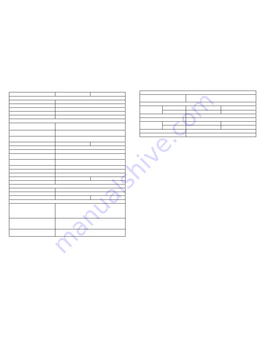
background image


34 

7  Specifications 

Model 5000VA/6000VA 

10000VA 

INPUT 

 Voltage Window 

160~280Vac* 

  Frequency 

45 ~ 65 Hz 

  Phase/Wire 

Single, Line + N Ground 

  Power Factor   

Up to 0.99 at 100% Linear Load 

  Current THD   

<5% at 100% Linear Load 

OUTPUT 

  Voltage Window 

220/230/240Vac Selectable

(208/120Vac 

optional)


 Voltage Adjustment 


±

0%; 

±

1%; 

±

2%; 

±

3% 

 Voltage Regulation  

±

2% 

 Capacity  

3500W/4200W 

7000W 

  Rated Power Factor   

0.7 Lagging 

  Wave Form   

Sine Wave, THD<3%(no load to full load) 

 Frequency Stability  

±

0.2%(Free Running) 

 Frequency Regulation  

±

1%; 

±

3% 

 Transfer Time  

0ms 

 Crest Factor  

3:1 

  Efficiency(AC to AC, Normal) 

Up to 91% 

  Efficiency(AC to AC, ECO) 

Up to 97% 

Up to 93% 

 DC Start  

Yes 

BATTERY 

 Quantity  

20pcs 

 Voltage 

240Vdc 

  Recharge Time 

4 hours to 90% 

5 hours to 80% 

DISPLAY 

  Status On LED + LCD 

Line Mode, Backup Mode, ECO Mode, Bypass 
Supply, Battery Low, Battery Bad/Disconnect, 
Overload, Transferring with interruption & UPS 
Fault.   

  Readings on LCD   

Input Voltage, Input Frequency, Output 
Voltage, Output Frequency, Load Percentage, 
Battery Voltage & Inner Temperature. 

Self-Diagnostics   

Upon Power-on, Front Panel Setting & 
Software Control, 24-hour routine checking 


35


ALARMS 

  Audible and Visual   

Line Failure, Battery Low, Transfer to Bypass, 

System Fault Conditions 

PHYSICAL 

power module


440x88x680 440x176x680 

Dimensions 

(HxWxD)mm 

With batteries 


440x176x680 x 

Input/Output Connection 

Hardwire 

  External Battery Connection 

Plug-in & Play   

Power module 

33 35 

Net Weight 

(Kgs),  

With battery   

55 x 

Leakage Current 

< 3mA at Full Load 

Marks 

CE, cUL, UL 


***These cards are not suitable to use simultaneously. 


Summary of Contents for 1_1 online mp series

Page 1: ...cation Port Explanation 11 3 Installation and Operation 12 3 1 Unpacking 12 3 2 Selecting Installation Position 13 3 3 Installation of Accessories Kit 14 3 4 Terminal Block Explanation 15 3 5 Operatio...

Page 2: ...ept in top condition 1 1 19 This UPS supports electronic equipment in offices telecommunications process control medical and security applications Non authorized technician is not allowed to install t...

Page 3: ...te control and monitoring easily 2 1 8Maintenance free sealed type battery minimizes after sales service 2 1 9Providing four different working modes such as Normal ECO CF50 and CF60 it may widely be u...

Page 4: ...verloading 31 Er14 Fan Error 32 Er15 Wrong Procedure to Enter Maintenance Mode 33 Er16 Output Parameters Set Error in Parallel System 34 Er17 ID Numbers are in conflict in Parallel System or ID number...

Page 5: ...us page or change the setting of the UPS To reconfirm the change of UPS Setting 9 2 3 2Rear Panel Explanation 5 6k PM 10K PM CB 1 Utility Input Breaker L12 N1 G1 L21 N22 G2 OUTPUT INPUT ON OF F S1 Ext...

Page 6: ...SNMP card you may combine them according to your demand However the R2E card RSE card and USE card are prohibited to be used simultaneously The bundled software of the UPS is compatible with many ope...

Page 7: ...s Wire No 7 is to be used at the input output terminal block of the UPS Please refer to Chapter 3 4 for installation A1 A2 A3 S1 S2 S3 S4 B1 B2 B3 x8 x6 x4 x2 x2 x2 x2 x1 x4 x4 for 2U for 3U PM10K onl...

Page 8: ...l Block Explanation L11 L12 N1 G1 L21 L23 N21 L22 N22 G2 OUTPUT INPUT BYPASS INPUT UTILITY INPUT L11 N1 BYPASS INPUT L12 N1 UTILITY INPUT G1 INPUT EARTH GROUND N22 L22 N21 L23 L21 UPS OUTPUT G2 OUTPUT...

Page 9: ...t Ground Use Mounting Cable Tie to fix cables Please refer to the specs of input current output current and recommended conductors listed as below a AC input and output b Battery input Model Maximum C...

Page 10: ...nputs are normal and the LCD display with parallel function will illustrate from drawing A1 drawing A2 to drawing B Otherwise the LCD display will illustrate from drawing A2 to drawing B A1 A2 B 19 3...

Page 11: ...ing G to drawing H then the UPS will be in self test Mode The UPS may offer energy to the output in a minute and the LCD display illustrates as drawing I In case of failure in pushing the UPS On Switc...

Page 12: ...pad to change the LCD display screen to drawing Q1 Q1 It shows buzzer On Q2 It shows buzzer Off 3 5 4 2 Press key pad to scroll down the screen and check the UPS settings The LCD display will show in...

Page 13: ...S2 It shows bypass voltage is adjusted to wider one T It shows Frequency Window is 3Hz 25 U It shows inverter output voltage V1 It shows the UPS is operated in normal mode V2 It shows the UPS is opera...

Page 14: ...ng T means the bypass frequency window of the Inverter Output the acceptable setting values are 3Hz and 1Hz 3 5 5 6 Drawing U means the acceptable Inverter Output Voltage of which voltage is 200Vac 20...

Page 15: ...e wirings of input and output correct b If the input voltage of the Utility is within the input window of the UPS In case problems or symptoms still exist please proceed the followings for proper adju...

Page 16: ...5 6 to trouble shoot the problem otherwise consult your local distributor for help 31 5 Bundled Software Installation Guide 5 1 Hardware Installation 1 Connect the male connector of RS232 cable to th...

Page 17: ...rmal Normal open contact Pin 4 Inverter On Pin 5 Battery Low Pin 6 Battery Bad or Abnormal Pin 7 UPS Alarm Pin 8 Common Pin 9 Shutdown UPS positive signal Pin 10 Shutdown UPS positive signal 6 4 2The...

Page 18: ...tage 240Vdc Recharge Time 4 hours to 90 5 hours to 80 DISPLAY Status On LED LCD Line Mode Backup Mode ECO Mode Bypass Supply Battery Low Battery Bad Disconnect Overload Transferring with interruption...

Page 19: ...36 192321132015003...

Reviews: