


18
3.5.
Operation Test and Installation Instruction
3.5.1 Start Up in Normal Mode
3.5.1.1
Open the terminal block cover on the rear panel (refer to 2.3.2) Before
start the installation, please make sure the grounding is connected properly.
3.5.1.2
Make sure Utility breaker, UPS’ Utility breaker is On “Off” position.
3.5.1.3
Make sure the voltage of Utility matches with the input voltage window of
the UPS.
3.5.1.4
Connect the Utility separately to the terminal blocks of UPS’ Utility and
Bypass Inputs. Switch on the Power Breaker of the distribution panel and the
breakers of the UPS’ Utility and Bypass Inputs, and then the UPS starts up.
Green LEDs
&
light up to show the Utility and Bypass Inputs are
normal and the LCD display with parallel function will illustrate from drawing
A1, drawing A2 to drawing B. Otherwise the LCD display will illustrate from
drawing A2 to drawing B.
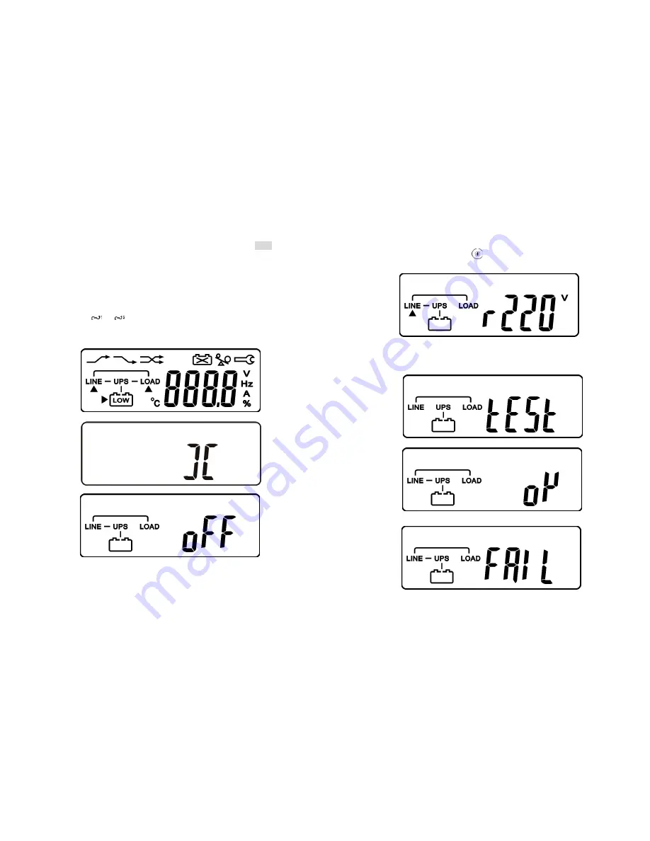
A1.
A2.
B.
19
3.5.1.5
Then, the UPS is on Bypass Mode now and it will proceed self-test
automatically. If there is no abnormal message occurred, it means the pre-
startup of the UPS is successful and the charger starts to charge the
batteries.
3.5.1.6
Press the UPS On Switch
for approx. 3 seconds, then the Buzzer
sounds twice and the LCD display changes from drawing B to drawing C.
3.5.1.7
C
3.5.1.8
Then, the UPS is under self-test mode again, the LCD display will
illustrate from drawing C to drawing D and remain approx. 4 seconds under
battery mode, then illustrate from drawing E1 to drawing F if the self-test is
successful.
D
* It shows “test”.
E1
* It shows “OK” in self-test
E2
* It shows “Fail” in self-test
Summary of Contents for 1_1 online mp series
Page 19: ...36 192321132015003...


