background image


26 


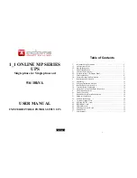
* It shows Output Voltage Adjustment % from 0% to 3% or -0% to -3%.   


* It shows UPS Identification Number.   


* It shows the UPS is in the No. 1

st

 of parallel systems.   


3.5.4.3 

Press scroll up 

  key pad, you may execute special functions. The 

Functions includes buzzer ON (as drawing Q1), or buzzer OFF (as drawing 
Q2, Alarm silence for UPS Warning) and self-test OFF (As drawing R1) or 
self-test ON. (as drawing R2. UPS will execute battery test for 10 seconds. If 
the self-test is successful, it will show as Drawing E1; otherwise, it will show 
as drawing E2 & error message in the same time.) 


3.5.5 UPS Default Settings and their alternatives 


3.5.5.1 

Make sure the UPS is not “On” yet. Press On Switch 

 and scroll 

down 

    key pads simultaneously for approx. 3 seconds, the buzzer will 

sound twice, the LCD display screen shows as drawing Q1, then the UPS is 
under setting mode now. 

3.5.5.2 

To scroll down the LCD screen, you may refer to Chapter 3.5.4.2  

3.5.5.3 

Except Buzzer(as drawing Q1 & Q2) and Self-test(as drawings R1 & R2), 

all the rest default settings may be changed by pressing scroll up 

 key 

pad. 


27

3.5.5.4 

Drawings S1 and S2 mean the bypass input acceptable window, it can 

be 184Vac~260Vac or 195Vac~260Vac. 

3.5.5.5 

Drawing T means the bypass frequency window of the Inverter Output, 

the acceptable setting values are ±3Hz and ±1Hz. 

3.5.5.6 

Drawing U means the acceptable Inverter Output Voltage, of which 

voltage is 200Vac, 208Vac, 220Vac, 230Vac, or 240Vac. 

3.5.5.7 

Drawing V1, V2, V3 and V4 mean the operation modes of the UPS, of 

which alternative is Online, Eco(Economic) mode, fixed 50Hz Output or fixed 
60Hz Output. 

3.5.5.8 

Drawing W means the adjustments of the Inverter Output, which may be 

calibrated as 0%, +1%, -1%, +2%, -2%, +3%, or -3%. 

3.5.5.9 

Drawing X means a specified address & position of the UPS when the 

UPS is in Parallel mode. The settable numbers are from 1st to 4th. The 
number must be 1

st

 if the UPS is not in parallel.     

3.5.5.10  Drawing Y means the parallel function status. The “P 01” means parallel 

function disabled and the “P02” means parallel function enabled. 

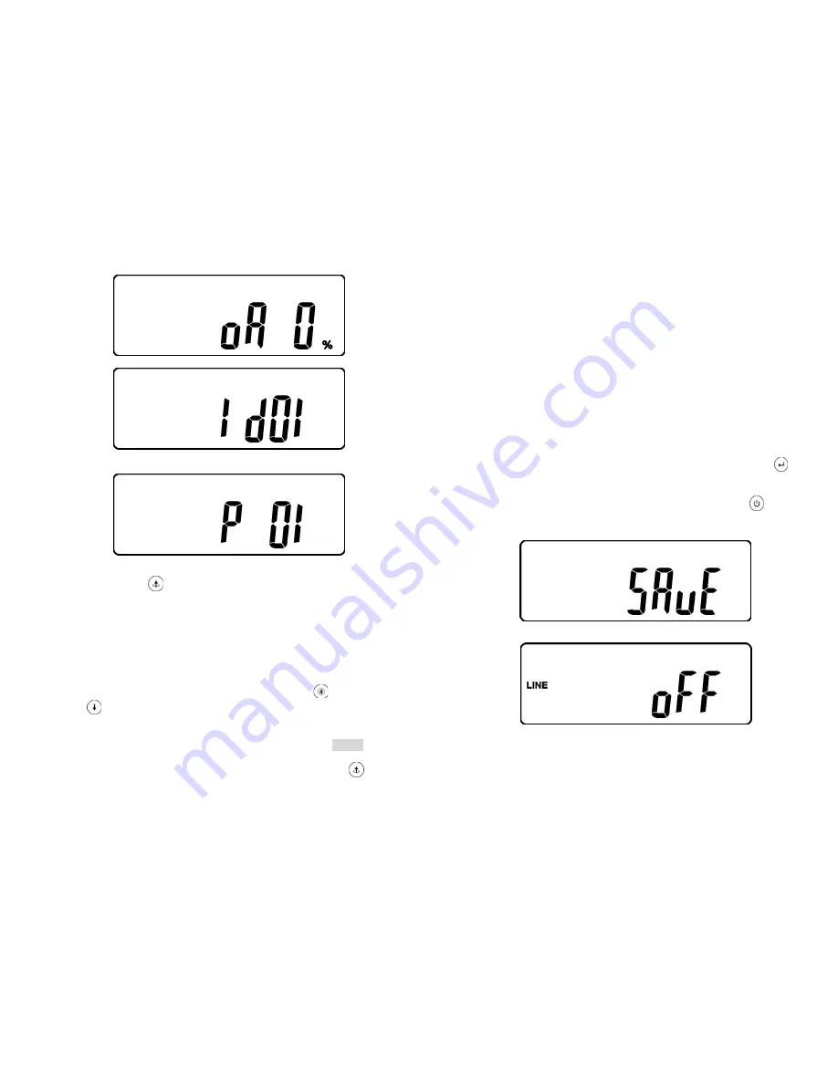
3.5.5.11  When all the setting changes are done, you have to press enter 

 key 

Pad to save all the changes when the LCD screen shows as drawing Z, then, 
the LCD screen will show as drawing AA to complete the setting changes. If 

you don’t want to change those settings, you may press “OFF” 

 key pads 

for 5 seconds, then the LCD screen turns to Drawing AA directly, which 
means your setting changes are invalid. 


  * Please press Enter key to save data. 


AA 


* It shows the UPS is locked.   

3.5.5.12  Turn Off the breaker of Utility Input. 
3.5.5.13  Your Setting changes are complete. 

Summary of Contents for 1_1 online mp series

Page 1: ...cation Port Explanation 11 3 Installation and Operation 12 3 1 Unpacking 12 3 2 Selecting Installation Position 13 3 3 Installation of Accessories Kit 14 3 4 Terminal Block Explanation 15 3 5 Operatio...

Page 2: ...ept in top condition 1 1 19 This UPS supports electronic equipment in offices telecommunications process control medical and security applications Non authorized technician is not allowed to install t...

Page 3: ...te control and monitoring easily 2 1 8Maintenance free sealed type battery minimizes after sales service 2 1 9Providing four different working modes such as Normal ECO CF50 and CF60 it may widely be u...

Page 4: ...verloading 31 Er14 Fan Error 32 Er15 Wrong Procedure to Enter Maintenance Mode 33 Er16 Output Parameters Set Error in Parallel System 34 Er17 ID Numbers are in conflict in Parallel System or ID number...

Page 5: ...us page or change the setting of the UPS To reconfirm the change of UPS Setting 9 2 3 2Rear Panel Explanation 5 6k PM 10K PM CB 1 Utility Input Breaker L12 N1 G1 L21 N22 G2 OUTPUT INPUT ON OF F S1 Ext...

Page 6: ...SNMP card you may combine them according to your demand However the R2E card RSE card and USE card are prohibited to be used simultaneously The bundled software of the UPS is compatible with many ope...

Page 7: ...s Wire No 7 is to be used at the input output terminal block of the UPS Please refer to Chapter 3 4 for installation A1 A2 A3 S1 S2 S3 S4 B1 B2 B3 x8 x6 x4 x2 x2 x2 x2 x1 x4 x4 for 2U for 3U PM10K onl...

Page 8: ...l Block Explanation L11 L12 N1 G1 L21 L23 N21 L22 N22 G2 OUTPUT INPUT BYPASS INPUT UTILITY INPUT L11 N1 BYPASS INPUT L12 N1 UTILITY INPUT G1 INPUT EARTH GROUND N22 L22 N21 L23 L21 UPS OUTPUT G2 OUTPUT...

Page 9: ...t Ground Use Mounting Cable Tie to fix cables Please refer to the specs of input current output current and recommended conductors listed as below a AC input and output b Battery input Model Maximum C...

Page 10: ...nputs are normal and the LCD display with parallel function will illustrate from drawing A1 drawing A2 to drawing B Otherwise the LCD display will illustrate from drawing A2 to drawing B A1 A2 B 19 3...

Page 11: ...ing G to drawing H then the UPS will be in self test Mode The UPS may offer energy to the output in a minute and the LCD display illustrates as drawing I In case of failure in pushing the UPS On Switc...

Page 12: ...pad to change the LCD display screen to drawing Q1 Q1 It shows buzzer On Q2 It shows buzzer Off 3 5 4 2 Press key pad to scroll down the screen and check the UPS settings The LCD display will show in...

Page 13: ...S2 It shows bypass voltage is adjusted to wider one T It shows Frequency Window is 3Hz 25 U It shows inverter output voltage V1 It shows the UPS is operated in normal mode V2 It shows the UPS is opera...

Page 14: ...ng T means the bypass frequency window of the Inverter Output the acceptable setting values are 3Hz and 1Hz 3 5 5 6 Drawing U means the acceptable Inverter Output Voltage of which voltage is 200Vac 20...

Page 15: ...e wirings of input and output correct b If the input voltage of the Utility is within the input window of the UPS In case problems or symptoms still exist please proceed the followings for proper adju...

Page 16: ...5 6 to trouble shoot the problem otherwise consult your local distributor for help 31 5 Bundled Software Installation Guide 5 1 Hardware Installation 1 Connect the male connector of RS232 cable to th...

Page 17: ...rmal Normal open contact Pin 4 Inverter On Pin 5 Battery Low Pin 6 Battery Bad or Abnormal Pin 7 UPS Alarm Pin 8 Common Pin 9 Shutdown UPS positive signal Pin 10 Shutdown UPS positive signal 6 4 2The...

Page 18: ...tage 240Vdc Recharge Time 4 hours to 90 5 hours to 80 DISPLAY Status On LED LCD Line Mode Backup Mode ECO Mode Bypass Supply Battery Low Battery Bad Disconnect Overload Transferring with interruption...

Page 19: ...36 192321132015003...

Reviews: