ACTUATECH RP10 Instruction Manual Download Page 1

EN - 

1

IT

EN

DE

FR

ES

RU

ACTUATECH S.p.A.

Via S. Lorenzo, 70, 25069 Villa Carcina (BS) Italy

Ph.

 +39 030 8908142  •  

Fax

 +39 030 8908143  •  [email protected]  •  

www.actuatech.com

Reference MAN81566 - 05/21

INSTRUCTION MANUAL

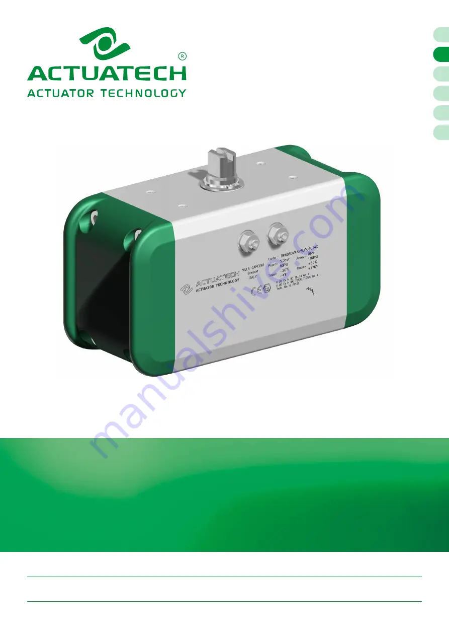
RP: RACK & PINION PART TURN PNEUMATIC ACTUATOR

DOUBLE ACTING (DA) AND SPRING RETURN (SR)

RP10 - RP480

Summary of Contents for RP10

Page 1: ...nzo 70 25069 Villa Carcina BS Italy Ph 39 030 8908142 Fax 39 030 8908143 actuatech actuatech com www actuatech com Reference MAN81566 05 21 INSTRUCTION MANUAL RP RACK PINION PART TURN PNEUMATIC ACTUATOR DOUBLE ACTING DA AND SPRING RETURN SR RP10 RP480 ...

Page 2: ... OPENING AND CLOSING ANGLE SETTING 14 9 MATERIALS AND DURABILITY 18 10 MAINTENANCE 21 11 ATEX SPECIFICATIONS 29 12 ACTUATORS SPECIAL VERSIONS 30 13 STORAGE 30 14 TROUBLE SHOOTING 30 15 DISPOSAL OF PRODUCTS AT THE END OF THEIR LIFE CYCLE 31 16 DECLARATION OF CONFORMITY 31 17 ENVIRONMENT IMPACT 31 Environmentally friendly under the green leaf icon you can find the instructions for a correct and envi...

Page 3: ... Pinon actuators have a decreasing rectilinear torque curve The components for the actuator maintenance are supplied in the ACTUATECH spare part kit see section 9 exploded views Actuators maintenance should be done by ACTUATECH or trained personnel only see section 10 This instruction manual contains important information regarding operation installation maintenance and storage of ACTUATECH actuat...

Page 4: ...e connection solenoid valve performance valve torque and characteristics ambient temperature condition Double Acting 0 90 cycle time ms 90 0 cycle time ms RP10 23 21 RP20 73 47 RP40 131 110 RP60 160 120 RP80 189 130 RP120 137 125 RP160 183 177 RP240 304 288 RP300 383 354 RP480 522 455 Ambient temperature 18 25 C 64 4 77 F Supply pressure compressed air 5 5 bar 80 psi for double acting and 6 bar 87...

Page 5: ...re suitable for indoor and outdoor installation Aluminium cylinder has an external corrosion pro tection realized by a 20µm technical oxidation layer Casted aluminium end caps are polyester painted The nickel plated transmis sion shaft Grub screw and caps screws are in stainless steel Actuators for aggressive or severe environment applications are available please contact us 2 10 Functional Safety...

Page 6: ... GAS threaded on the cylinder for RP300 and RP480 NPT threaded on the cylinder from RP10 to RP480 Threaded holes according to VDI VDE 3845 to connect eventual accessories Adjustment grub screw for closing and opening setting 5 closing setting from 5 to 5 opening setting from 85 to 95 Bi square Drive Valve connection flange Evacuation grooves in case of shaft leakages 1 2 3 4 5 6 7 8 9 10 Customiza...

Page 7: ...G G Springs used 00 No springs 20 2 0 bar springs 25 2 5 bar springs 30 3 0 bar springs 35 3 5 bar springs 40 4 0 bar springs 45 4 5 bar springs 50 5 0 bar springs 55 5 5 bar springs 60 6 0 bar springs H H Smaller Flange Type 03 F03 04 F04 05 F05 07 F07 10 F10 12 F12 I Lower shaft seat shape socket Q Star shaft D Flat head shaft J J Lower shaft seat size socket 09 Shaft dimension 9mm 11 Shaft dime...

Page 8: ... rotates clockwise CW to close the valve 5 2 Spring Return SR FAIL TO CLOSE Supplying air into port 2 pistons move outward compressing the springs and actuator shaft rotates counter clockwise CCW to open the vale Closing action is realized stopping air feeding Springs energy push pistons back and consequently shaft rotates clockwise CW To avoid dust or solid particles incoming close port 4 using a...

Page 9: ...se of explosive environment use protection caps in complian ce with National safety or technical Standards 5 4 Connection diagram Remote operation control should be done connecting a direct solenoid valve to VDE VDI 3845 NAMUR plate or connecting a piping system directly to ports 2 4 Use an independent electric control cabinet According with ISO 5599 2 Standard actuator ports connection position l...

Page 10: ...red responsible for any damage to people animals or things due to an improper use of the product 7 INSTALLATION INSTRUCTIONS Before actuator installation check its conditions to verify eventually failure during transport and or storage Actuator purpose is a remote control of a valve opening and closing actions avoiding manual operations Actuator uses air or gas controlled by a mechanic pneumatic o...

Page 11: ...ion A Pull reduction in valve stem in case of reduction needs only B Put valve stem into the actuator socket C Verify correct connection to avoid play clearance or interferences in between D Place screws 1 and relevant washers 2 and screw them in compliance with below torque indications E After installation check actuator rotation direction for Double acting DA actuators F After installation check...

Page 12: ...ation grooves on connection side is purposely designed to a direct installation Evacua tion grooves avoid any actuator damages caused by eventual draining fluids coming from valve stem Installation A Place Bracket 4 on valve flange ribs must be perpendicular to the pipe B Place screws 1 and relevant washers 2 C Place nuts 7 and washers 8 and in correspondence to the screws D Lock the nuts using a ...

Page 13: ...r Valve controls Rotation direction check and installation Double acting DA Closed valve Spring Return SR Fail Close Closed valve Double acting DA Opened valve Spring Return SR Fail Close Opened valve Rotazione oraria dell albero Clockwise rotation of the shaft 4 Rotazione oraria dell albero Clockwise rotation of the shaft 4 Counter clockwise Rotazione antioraria dell albero rotation of the shaft ...

Page 14: ...with a 5 adjusting stroke closing setting from 5 to 5 and opening setting from 85 to 95 Before any operation take the pressure off disconnect air feeding and make sure that air ports have been completely vented A B A B GRANO DADO O ring RONDELLA CAMMA Adjusting screw nuts Size Thread Grub screw key Nut key Torque Nm RP 10 M6 ch 3 ch 10 10 11 RP 20 RP 40 RP 60 M8 ch 4 ch 13 22 25 RP 80 RP 120 RP 16...

Page 15: ...position E Using an Allen wrench screw or unscrew grub screw A to obtain angle setting required range 5 F Once adjusted lock the grub screw A using an Allen wrench and screw counter nut A1 according to torque indications Closing Setting instructions A Take pressure off disconnect air feeding and make sure that air ports have been completely vented B Act on the grub screw see arrow C Unloose counte...

Page 16: ...mall movement only in order to put pistons in end position F Using an Allen wrench screw or unscrew grub screw A to obtain angle setting required range 5 G Once adjusted lock the grub screw A using an Allen wrench and screw counter nut A1 according to table torque indications Setting range Pistons end position Closing Setting instructions A Take pressure off disconnect air feeding and make sure th...

Page 17: ... grub screw A to obtain angle setting required range 5 F Once adjusted lock the grub screw A using an Allen wrench and screw counter nut A1 according table torque indications Setting range Pistons rest position Closing Setting instructions A Take pressure off disconnect air feeding and make sure that air ports have been completely vented B Make sure that on air port 4 has been assembled a filter a...

Page 18: ... vane actuator Minimum number of cycles b Maximum stroking time for testing based on 0 90 s 125 500 000 c 3 1 000 500 000 5 2 000 250 000 8 8 000 100 000 15 32 000 25 000 20 63 000 10 000 30 125 000 5 000 45 250 000 2 500 60 a Based on EN ISO 5211 b One cycle consists of nominal 90 angular travel in both directions i e 90 to open 90 to close For angular travel other than 90 the endurance shall be ...

Page 19: ...1 Acetal resin 8 External support ring 1 Acetal resin 9 Washer 1 Stainless steel 10 Seeger 1 Stainless steel 11 O Ring 2 Nitrile rubber 12 O ring upper sealing shaft 1 Nitrile rubber 13 Namur plate 1 Aluminium alloy 14 Screw 2 Stainless steel 15 O Ring 2 Nitrile rubber 16 Washer limit stroke 2 Stainless steel 17 Nut limit stroke 2 Stainless steel 18 Grub screw limit stroke 2 Stainless steel 19 Pis...

Page 20: ...1 O Ring 2 Nitrile rubber 12 O ring upper sealing shaft 1 Nitrile rubber 13 Namur plate 1 Aluminium alloy 14 Screw 2 Stainless steel 15 O Ring 2 Nitrile rubber 16 Washer limit stroke 2 Stainless steel 17 Nut limit stroke 2 Stainless steel 18 Grub screw limit stroke 2 Stainless steel 19 Piston 2 Aluminium alloy 20 Piston support leg 4 Acetal resin 21 Dynamic seal 2 Polyurethan 22 O Ring 2 Nitrile r...

Page 21: ...ected from the valve Spare parts must be replaced by qualified personnel and with appropriate tools only In the case of Spring return actuators the springs can be under tension Do not attempt to act manually on the actuator when the actuator is under pressure In case of Spring return actuator springs must be in FAIL position Do not disconnect the actuator from a line under pressure or if still und...

Page 22: ... Remove washer 16 and O Ring 15 Check counter nut and grub screw D Lock the actuator into a vice rotate the shaft see below pictures until pistons look completely free from shaft gear then remove the pistons from the cylinder Do not use air to remove the pistons it might cause severe personal injuries E Check dynamic seal 21 and piston support leg 20 Do not use sharped tools to replace the compone...

Page 23: ...er 9 from external support ring 8 from cylinder using a flat bladed screwdriver H Pull down shaft 2 as shown in below picture During this process hold cam 6 and internal support ring 7 Cam fall could cause irreversible scrapes or grooves in cylinder inner surface I Pull up O ring 12 and slide ring 3 and remove them J Pull down O ring 5 and slide ring 4 and remove them k Do not use sharped tools to...

Page 24: ... with Namur plate see section 3 M Disassembled components must be cleaned and verified before reassembly In case of advanced state of wear o break replace the components using ACTUATECH replacement Kit If it is necessary to replace parts not present in the spare part kit contact ACTUATECH Degreasing process must be done using only specific cleaners suitable for rubber Do not use solvents they will...

Page 25: ...ightening surface 21 Lubricate piston support leg 20 and put them on relevant seats C Lubricate O ring 12 5 and slide rings 3 4 D Grease piston gear slide rings seats and shaft O Ring 2 E Pull down upper slide ring 3 and O Ring 12 see beside image F Pull up lower slide ring 4 and O ring 5 see beside image G Slide rings and O Rings must be assembled manually do not use sharped tools to replace the ...

Page 26: ...xternal support ring 8 and washer 9 K Pull up the shaft in the lower cylinder hole then insert cam 6 and internal support ring 7 according to below instructions L Pull up the shaft in the upper cylinder hole and insert external support ring 8 washer 9 and Seeger 10 M According to actuator configuration place shaft 2 and cam 6 as below indicated 10 9 8 1 7 6 2 Double Acting DA and Spring Return Fai...

Page 27: ...ch rotate the shaft to verify Easy shaft rotation Correct rotation direction Closing angle range 0 5 looking at shaft slot Opening angle range 90 5 looking at shaft slot Q For Spring Return SR actuators follow the further indications 19 2 Tool Model Spring quantity Spring location on pistons sx dx Piston Left Right RS20 4 2 5 1 2 5 3 6 4 2 5 1 2 5 3 6 4 RS25 5 2 5 1 2 5 3 6 4 2 4 6 1 2 5 3 6 4 RS3...

Page 28: ...O ring 15 T Screw hexagon nut 17 for some threads on grub screw 18 insert washer 16 and O Ring 15 along the grub screw 18 U Screw grub screw with pre assembled components in cylinder threaded hole using an Allen wrench Pay attention screw starting form rounded end grub screw V See angle setting procedure on section 8 W Grease O Ring 11 X Rest Namur plate 13 to cylinder surface 1 and fasten screws ...

Page 29: ...s Classification and Zone Classification A Equipment classification Equipment Group II Category 2 Gas Zone 1 2 Dust Zone 21 22 Type of protection Ex h with constructional safety c Gas group IIC IIB with non conductive coating thickness 0 2mm Dust group IIIC Temperature Class T6 T3 as per following table EPL Gb Gas Db Dust T max fluid and T max ambient Temperature Class Max surface temperature 50 C...

Page 30: ...ded to keep actuators in a dry and clean environment at temperatures 10 C 60 C 14 F 140 F Actuators have two air ports which are closed by labels for prevent dust or solid particles incoming during storage If actuators should be stored for a long period before installation it is recommended to stroke them periodically to prevent seals damages 14 TROUBLE SHOOTING Potential effect of failure Potenti...

Page 31: ...mponents aluminium steel can be recovered disposed as raw material Sealing elements such as O Ring or Gaskets NBR FPM FVMQ as contaminated by fluids or lubricants must be disposed of Packaging materials should be transferred to separate waste collection system available in the Country 16 DECLARATION OF CONFORMITY ACTUATECH S p A actuators have been designed manufactured and tested to meet the requ...

Reviews: