


Installation and Commissioning Guide
Hercules Package Unit
33
Installation and Commissioning Guide - Hercules Package Unit
Doc. No.0525-021
Ver. 21 221110
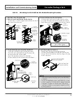
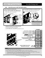
15.02.03. Relocating Control Interface Into Remote Mounting Procedure
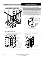
1. Open Access-Door Control Section
2. Remove Access Panel-Electrical Isolator Section
• Perform steps 1 - 2 of Main Supply Cable Installation section to
gain access to control panel.
1
ACCESS
DOOR -
CONTROL
QUARTER
TURN LOCKS
CONTROL
INTERFACE
2
ACCESS PANEL
ELECTRICAL
LOCK
SCREWS
ACCESS DOOR
CONTROL
CONTROL
PANEL
CM100
CONTROLLER
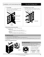
3. Remove and Disconnect Control Interface
• Unscrew and Pull-out Control Interface from mounting.
• Disconnect RJ12 plug from Control Interface and Control
Board. (Remove or tuck-in control cable into Duct-Slotted).
RJ12 PLUG
CONTROL
INTERFACE
CONTROL CABLE
See Interface removal
instructions on succeeding steps.
RJ12 PLUG
CM100
CONTROLLER
DUCT-
SLOTTED
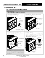
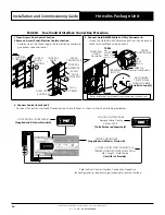
4. Thread and Route new control cable into the Unit
• Pierce hole in rubber grommet to allow cable access.
• Thread the new control cable through the access hole.
• Route the new cable, as shown above.
• Secure the new cable with wire ties and clamps.
• Connect cable to Control Interface and Control Board.
CONTROL
CABLE
Mount
Control Interface
to remote location
CM100
CONTROLLER
RJ12 PLUG
DATA
ACCESS
POWER SUPPLY
ACCESS
RJ12 PLUG
5. Control Interface Removal Instructions
• Remove Cover from Control Interface main body.
• Unscrew Control Interface main body from control panel.
• Pull-out Control Interface from panel mounting and unplug
the RJ12 connector.
Screw
(2-off)
Unscrew Control Interface
from Control Panel
Remove Cover from
Control Interface
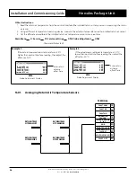
NOTES
• See Control Interface insert for panel cut-out dimensions
and details.
• For control cable length in excess of 50 METERS, a 6 Core
(3 Pair) Twisted Pair 7.0/0.20 (AWG24) Shielded Data Cable
is required. This cable must also be used if the control
interface is installed in an environment subject to ACMA
EMC requirements.


