


Installation and Commissioning Guide
Hercules Package Unit
23
Installation and Commissioning Guide - Hercules Package Unit
Doc. No.0525-021
Ver. 21 221110
*
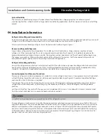
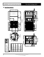
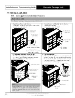
Airflow clearance of 1200 mm is for open air space installation, a minimum of 2500 mm airflow clearance must be
provided for close space areas with walls higher than the unit.
Please note that under all circumstances, condenser
air must not recirculate back onto condenser coil.
**
Preferred service access for indoor coil should service access be required on the opposite side, the two side clearances
will swap with the same condition applied for small clearance side.
***
Minimum height clearances for installation with limited service clearance are as follows:
-1500 mm, if 2500 mm service clearance for indoor coil is available on both sides of the unit.
-2500 mm, if 2500 mm service clearance for indoor coil is not available on either side of the unit.
****
For units with optional economy air and spill air, provide 300 mm clearance between the hood and the other unit or
wall.
11. Unit Preparation
SAFETY INSTRUCTIONS
Only licenced service personnels are allowed to perform the procedures described in this guide.
WH&S regulations must be observed and will take precedent during the assembly and installation procedure.
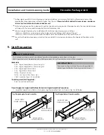
Materials:
• 2 Pcs - Angle (Supply/Return) Down Long-LH
• 2 Pcs - Angle (Supply/Return) Down Long-RH
• 2 Pcs - Angle Supply Down Short
• 2 Pcs - Angle Return Down Short
• 30 Pcs - Rivets ø 4 x 8 mm
• 34 Pcs - Set Screws M8 x 30 mm Hex
• 1 Roll - Insulation Tape 3.2 x 6 mm Black
Tools Required (Not Supplied):
• Rivet Gun and Socket Wrench
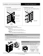
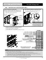
IMPORTANT NOTE
For proper sealing, Insulation Tape must be applied to
adjoining contact before fastening rivets and screws.
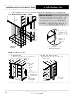
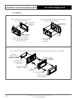
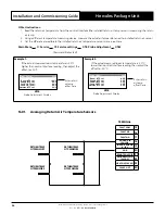
Down Supply Air Angle And Bottom Return Air Angle Assembly Procedures:
1. Assemble Supply Air and Return Air angles using the provided rivets as shown in Fig. 1 and 2 below:
Fig.1 Angle Supply Down Assembly
ANGLE SUPPLY
DOWN LONG-LH
ANGLE SUPPLY
DOWN LONG-RH
ANGLE SUPPLY
DOWN SHORT X 2
RIVETS
Fig.2 Angle Return Down Assembly
ANGLE RETURN
DOWN LONG-LH
ANGLE RETURN
DOWN LONG-RH
ANGLE RETURN
DOWN SHORT X 2
RIVETS


