background image


24

 / 42


Identifying Library Module Components


If you have unpacked a Base Module, confirm that you have received the following components: 

1.  Base Module 

2.  Two Rack Rails 

3.  Accessory Kit 

a.

  One packet of rack mount hardware 

b.

  One North American Power Cord 

c.

  One European Power Cord 

If you have unpacked an Expansion Module, confirm that you have received the following components: 

1.  Expansion Module 

2.  Two Rack Rails 

3.  Accessory Kit 

a.

  One packet of rack mount hardware 

b.

  Expansion Interconnect Cable 

For SAS libraries, you must provide SAS cabling with the correct configuration for your HBA.  For Fibre 
Channel libraries, you must provide one Fibre Channel cable for each tape drive.   


Preparing Top and Bottom Modules


Skip this step if you are installing a Base Module only without an Expansion Module.   

The Base Module has a removable top and bottom covers.  

If you are installing one or more Expansion Modules above the Base Module, move the top cover from the 
Base Module to the Expansion Module that will be installed at the top of the library. 

If you are installing on or more Expansion Modules below the Base Module, move the bottom cover from 
the Base Module to the Expansion Module that will be installed at the bottom of the library. 

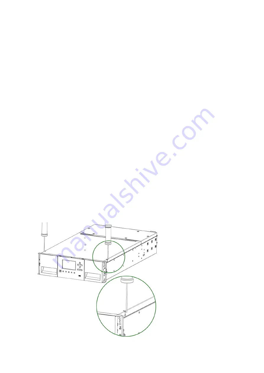
To move the library top cover plate from the Base Module to an Expansion Module: 

1.  Remove the library top cover plate from the Base Module.   

a.

  Place the Base Module on a work table 

b.

  Unlock the top cover using two small screwdrivers

.


Summary of Contents for actiLib Kodiak 3407

Page 1: ...view and information to install and the initial setup of the actiLib Kodiak 3407 Scalable Tape Library The instruction is intended for trained System Administrators and Users who need physical and functional knowledge of the actiLib Kodiak 3407 library actidata Storage Systems GmbH 07 12 2018 ...

Page 2: ...2 42 Revision Change No Author Verified by Release Date yyyy mm dd Description 1 0 0 Timo Kühne 2018 06 06 Initial Revision ...

Page 3: ...Planning Module and Rack Layout 19 Internal IP Range Selection 19 Host Preparation 20 Installation Precautions 21 Unpacking Base Module and Expansion Modules 22 Identifying Library Module Components 24 Preparing Top and Bottom Modules 24 Installing Modules in a Rack 27 Aligning and Connecting Modules 29 Installing Tape Drives 31 Connecting Fibre Channel Cables 31 Connecting SAS Cables 31 Powering ...

Page 4: ... Tape Cartridges 35 Write Protecting Tape Cartridges 36 Initial Setup of the Library 37 Using the OCP 37 Using the RMI 37 Logging into the Library 38 Using the Initial Configuration Wizard on the OCP 38 Get help 42 ...

Page 5: ...installation et l utilisation dans un rack d ordinateur avec les portes avant et arrière fermées et sécurisées Seul un personnel avec la formation technique et de sécurité des produits est autorisé à accéder à la bibliothèque Ce personnel est désigné par utilisateurs dans la totalité de ce document Pour des raisons de sécurité le PIN d administrateur par défaut doit être changé au cours de la conf...

Page 6: ...to equipment or data IMPORTANT Provides clarifying information or specific instructions NOTE Provides additional information TIP Provides helpful hints and shortcuts AVERTISSEMENT Le non respect de ces instructions expose l utilisateur à des risques potentiellement très graves ATTENTION Le non respect de ces instructions comporte des risques tant pour le matériel que pour les informations qu il co...

Page 7: ...entrainer de graves blessures Gardez les mains à l écart pendant le fonctionnement WARNING Product Weight Risk of personal injury Before lifting a module Observe local health and safety requirements and guidelines for manual material handling Remove all tapes to reduce the weight Remove all tape drives to reduce the weight Obtain adequate assistance to lift and stabilize the module during installa...

Page 8: ...Risk of damage to devices A discharge of static electricity damages static sensitive devices or micro circuitry Proper packaging and grounding techniques are necessary precautions to prevent damage ATTENTION Électricité statique Risque d endommager les périphériques par une décharge d électrostatique Une décharge d électricité statique peut endommager les circuits imprimés du système ou les autres...

Page 9: ...ion correspondant aux instructions figurant dans le mode d emploi ou comme directement indiqué sur le produit Protection du cordon d alimentation Placez le cordon d alimentation principal de sorte qu il ne soit pas possible de marcher dessus ou d être écrasé par des objets placés sur ou contre Pénétration d objets et de liquide S assurez que des objets ne tombent pas sur le boîtier du produit et q...

Page 10: ...h Base Module with capacity for 32 tape cartridges and 3 half height LTO tape drives actiLib Kodiak 3407 is expandable allowing a user to grow their tape storage capacity as their data requirements increase As data storage needs grow actiLib Kodiak 3407 can also grow by adding one or more 3U high Expansion Modules Each Expansion Module provides an additional 40 tape cartridges and supports an addi...

Page 11: ...uantity Supported Library Configurations 1 Module Library Base Module 2 Module Library Base Module 1 Expansion Module 3 Module Library Base Module 2 Expansion Modules 4 Module Library Base Module 3 Expansion Modules ...

Page 12: ...12 42 Module Quantity Supported Library Configurations 5 Module Library Base Module 4 Expansion Modules 6 Module Library Base Module 5 Expansion Modules 7 Module Library Base Module 6 Expansion Modules ...

Page 13: ...pe Drives actiLib Kodiak 3407 was developed to integrate industry standard LTO Ultrium tape drives from both HP and IBM Mixed drive generations and mixed interfaces are supported within a single library and within a single module Listed below are the tape drives that have been implemented and qualified for use in actiLib Kodiak 3407 IBM LTO Drives HP LTO Drives LTO 6 Half Height FC Single Port LTO...

Page 14: ... Base Module Only 8 Error LED Amber Base Module Only 9 USB Port Base Module Only 10 Operator Control Panel OCP Display Base Module Only 11 Back Return Button Base Module Only 12 Navigation Button Left Base Module Only 13 Navigation Button Up Base Module Only 14 Navigation Button Down Base Module Only 15 Navigation Button Right Base Module Only 16 Enter Button Base Module Only 17 Mailslot Right Mag...

Page 15: ...Drive Bays 4 Upper Expansion Module Connection Port 5 USB Port Optional on Base Module Only 6 Ethernet Port A Base Module Only 7 Ethernet Port B Optional on Base Module Only 8 Module Alignment Mechanism 9 Lower Expansion Module Connection Port 10 Unit Identifier LED Blue 11 Controller Error LED Yellow 12 Controller Health Status LED Green 13 Product Serial Number Tag Location ...

Page 16: ...e library will generally display logical element numbering of modules storage slots and tape drives starting with number one from the bottom up 1 Left Magazine 2 Right Magazine Mailslot Disabled 3 Right Magazine Mailslot Enabled ...

Page 17: ... 35º C 50 95º F Power Source AC Power Voltage 100 240 VAC Line Frequency 50 60 Hz Library Located near AC Outlet s The AC power cord is the library s main AC disconnect device and must be easily accessible at all times Air Quality Place the library in an area with minimal sources of particulate contamination Avoid areas near frequently used doors and walkways stacks of supplies that collect dust p...

Page 18: ...new tape drive The operating system tracks the WWID for the tape drive on each HBA channel Each of the drive connectors on the fan out cable is associated with an HBA channel Once a tape drive has been plugged in it should remain on the same channel to retain the association between the HBA channel and WWID Fibre Channel Configuration Requirements The Fibre Channel FC tape drive can be connected d...

Page 19: ... addresses it is required to select the internal IP range before the tape library gets connected to the external Ethernet port Therefore a file which contains the internal IP range is stored onto the Base Module backplane opt storage mfg stack network range and LCM opt storage configuration network range The Values must be in the following format RANGE 192 0 2 Please note the last section of the I...

Page 20: ... les circuits imprimés du système ou les autres périphériques sensibles aux décharges électrostatiques Un emballage approprié et une mise à la terre constituent les précautions nécessaires pour éviter tout dommage Follow these general guidelines Check with a system administrator before powering off the host computer For a SAS library confirm availability or install a SAS HBA that supports multiple...

Page 21: ...t a time CAUTION Do not expose the library to moisture Do not place a module on either the ends or sides as this may cause damage AVERTISSEMENT Poids du produit Chaque actiLib Kodiak 3407 module de bibliothèque pèse 20 kg sans média ni lecteur de bande et 35 kg avec média 40 cartouches et trois lecteurs de bande Lors du déplacement de la bibliothèque pour réduire les risques de blessures ou de dét...

Page 22: ... Kodiak 3407 Base Module or Expansion Module 1 Before opening and removing a module from the box inspect the container for shipping damage 2 If you notice any damage report it to the shipping company immediately 3 Unpack the module from the box and place it on a work table 4 Skip the next steps if you are installing an Expansion Module only 5 The robotics is protected during shipment by an inserti...

Page 23: ... If you are installing a Base Module only without an Expansion Module install the top cover again on the Base Module 10 If you want to install a library stack with multiple modules see chapter Preparing Top and Bottom Modules 11 Save the packaging materials for future use CAUTION Do not place a module on either the ends or sides as this may cause damage ...

Page 24: ...de one Fibre Channel cable for each tape drive Preparing Top and Bottom Modules Skip this step if you are installing a Base Module only without an Expansion Module The Base Module has a removable top and bottom covers If you are installing one or more Expansion Modules above the Base Module move the top cover from the Base Module to the Expansion Module that will be installed at the top of the lib...

Page 25: ... of the top cover until the latches engage on both sides To move the library bottom cover plate from the Base Module to an Expansion Module 1 Remove the library bottom cover plate from the Base Module a Place the Base Module on a work table b Lift the unit front end by about 16 cm use unit rear as a pivot edge c Support the the bottom cover with one hand Insert a small flathead screwdriver or Torx...

Page 26: ...e an Expansion Module a Place the Base Module on a work table b Lift the unit front end by about 16 cm use unit rear as a pivot edge c Insert the bottom cover at the center d Lift up the cover front edge until hard stop and it locks in at the unit front ...

Page 27: ...l module 3U higher To install the rails into the rack starting from the lowest rack location 1 Locate all the 4 adapter blocks 4 Philips screws and 2 rackmount rails LH and RH 2 On the front of the rack mount an adapter block at the appropriate height to the right and left rack posts Mount them in the middle square hole of the height unit The middle of a height unit is the hole between two wide an...

Page 28: ... multiple modules verify that this module has been installed directly above or below its adjacent module and is contained within the correct 3U volume The gap between modules must be less than 4 mm 3 Use a screwdriver for Phillips recess to tighten the screws on each side of the module 4 Repeat steps 3 through 5 to install the rest of the modules into the rack ...

Page 29: ...e locked position 1 From the front of the library loosen the screws on each of the modules two full turns 2 From the back of the library starting with the bottom pair of modules align each module with the module below Repeat for each pair of modules a Move the alignment lever to the lock position If you encounter resistance adjust the position of the upper module so the pin in the alignment mechan...

Page 30: ...ism in the unlocked position 4 From the front of the library tighten the Philips screws on each of the modules to secure the modules to the rack 5 From the back of the library connect the modules of each pair to its adjacent module using the expansion interconnect cable as shown ...

Page 31: ...ue les doigts le tout pouvant entrainer de graves blessures Gardez les mains à l écart pendant le fonctionnement Connecting Fibre Channel Cables 1 Remove the FC port caps if necessary Attach one end of the FC cable to port A on the tape drive 2 Attach the other end of the FC cable to a switch or HBA Connecting SAS Cables 1 Attach the HBA end of the SAS cable into the connector on the HBA If you ar...

Page 32: ...configuration date and time and setting the administrator PIN You can skip items and stop the wizard at any time Once you have configured the network settings you can initiate the wizard from the RMI to complete the remaining configurations For Login to the RMI use the default Administrator Password adm001 Verifying the Host Connection To verify the connections between the host computer and the li...

Page 33: ...ot is enabled indicated by the right button LED steady ON you can use it to load cartridges into the library 1 Press the right button for less than 3 seconds This will start the unlock operation for the mailslot indicated by the LED slowly flashing 2 When the mailslot is unlocked the LED starts quickly flashing 3 Pull out the mailslot from the library As soons as the mailslot is pulled out the LED...

Page 34: ...the Installation Verify that the library has the current firmware revision The library firmware revision is displayed in the top left corner on the RMI screen or on the Home Status Library Library Status screen on the OCP If necessary update the library firmware from the OCP or RMI Maintenance Software Upgrades System Firmware screen After configuring the library you can save the configuration set...

Page 35: ...r the same length of time it was exposed to extreme temperatures or 24 hours whichever is less Do not place data cartridges near sources of electromagnetic energy or strong magnetic fields such as computer monitors electric motors speakers or X ray equipment Exposure to electromagnetic energy or magnetic fields can destroy data and the embedded servo code written on the media by the cartridge manu...

Page 36: ...e tape cartridge Never apply multiple labels onto a cartridge because extra labels can cause the cartridge to jam in a tape drive Write Protecting Tape Cartridges All rewriteable data cartridges have a write protect switch to prevent accidental erasure or overwriting of data Before loading a cartridge into the device make sure the write protect switch on the front of the cartridge is in the desire...

Page 37: ...ated together In addition UIDs on drives and expansion module back panels can be activated separately The UIDs are helpful for locating components of the library in a data center Ready Green steady when power is on blinking with tape Ready drive or library robotic activity Clean Amber when a tape drive cleaning operation is recommended Attention Amber blinking if the library has detected a conditi...

Page 38: ...ess to status information but not configuration maintenance or operation functions Administrator The administrator password is required to login as the administrator There is a default administrator password adm001 for the first login The administrator password can be changed in the Configuration Configure User Accounts page The administrator user has access to all functionality except for the log...

Page 39: ...e Finish Button Otherwise with every login on the OCP the user will be prompted again to walk through the wizard Once you have configured the network settings you can initiate the wizard from the RMI to complete the remaining configurations To login the very first time on the RMI you should use the default administrator password adm001 To set your own password go to the page Configuration User Acc...

Page 40: ...hcp NOT reset Default Gateway dhcp NOT reset Auto Negotiate Enable NOT reset Speed Auto NOT reset IPV4 Enabled NOT reset DHCPv4 Enabled NOT Reset IPV6 Disabled NOT reset IPv6 Prefix Enabled NOT reset Static V6 Disabled NOT reset IPv6Method Disabled NOT reset DHCPv6 Disabled NOT reset DNS1 and DNS2 Configuration for Ipv4 dhcp NOT reset DNS1 and DNS2 Configuration for IPv6 Disabled NOT reset Network...

Page 41: ...ail Notifications SMTP Disabled Yes SNMP SNMP v1 v2 v3 Disabled Yes Licensed Features need license for enablement Encryption KMIP Disabled NOT reset OCP Screen Preferences Screen Saver Default image Yes Activation 10 minutes Yes Image Customer specified Yes SCSI Defaults Product Name Marketing Name Yes Library Product ID INQUIRY Product ID String Kodiak 3407 Yes Library Vendor ID INQUIRY Vendor ID...

Page 42: ...t 30 minutes Yes RMI Restricted Login Disabled Yes DRIVE Defaults Drive speed and topology settings Automatic Automatic Yes Odometer Enabled NOT reset Get help The actiLib Kodiak 3407 Tape Library User and Service Guide will give you more details about how to install configure and use your Tape libraray to Specifications of your interest actidata Storage Systems GmbH Wulfshofstr 16 D 44149 Dortmun...

Reviews:

Related manuals for actiLib Kodiak 3407