background image

23 

Replacing the Circuit Board Batteries 

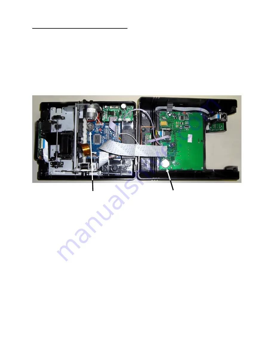
The ATR360 is equipped with (2) CR2032 3v Lithium Coin Cell batteries: one battery is on the 
Main board and the other is on the Display board.    The batteries should last approximately 1.5 to 
2 years under normal operating conditions.  Do not attempt to replace these batteries as it will 
void your warranty.  If your clock is already out of warranty you can attempt to replace the 
batteries yourself but note that you could damage the boards if you short out any components on 
the circuit board.    Avoid using metal objects to remove the batteries. 
Note: All Time Recorder settings will be reset to factory defaults as soon as the Main board battery 
is removed. 


                   Back Case                                Front Case 


                        Main Board Battery                                Display Board Battery 


1. Unplug clock. 
2.  Remove the front cover and the two screws that connect the front and back case.    Remove 

the front case and lay it flat being careful not to pull any wires or cables loose. 

3.  To remove batteries press the metal retaining clip away from the battery. The battery should 

pop up. It may be necessary to use a small probe to pop the battery out. 

4.  Replace the batteries and re-assemble clock. 


Summary of Contents for ATR360

Page 1: ...ATR360 User Manual Top Loading Time Recorder With Fingerprint Proximity Badge User Verification...

Page 2: ...ur warranty Battery replacement should be done by qualified personnel wearing the proper eye protection CAUTION Danger of explosion if the battery is incorrectly replaced Replace only with the same or...

Page 3: ...Table 7 Correct Finger Positioning on the Sensor 8 Finger Print Setup 8 Add User 9 Badge Setup 9 Important Setting the Real Time Clock RTC 10 Synchronizing the RTC to the System Clock 10 Fingerprint...

Page 4: ...18 Troubleshooting 19 Frequently Asked Questions 21 Maintenance 22 Replacing the Ribbon Cassette 22 Replacing the Circuit Board Batteries 23 Installing the Operational Battery Pack 24 Cleaning the ATR...

Page 5: ...g a ball point pen press the Reset button Do not attempt to service the ATR360 yourself Disassembling the clock will void the warranty Always follow the instructions in the user guide Do not place the...

Page 6: ...Sun 01 07 07 Clock Display Format 12 or 24 Hr 12 08 Adjust Printing Position Max 6mm Vert Horiz adj Increase s to move up right 00 15 Vertical Axis 00 30 Horiz Axis 08 08 vert horiz 09 DST Start Month...

Page 7: ...ock Overview Top View Front View Battery Status Indicator A fully charged Battery will have 5 bars DST Icon displays when exiting programming mode when DST is turned on Each blink of the colon is one...

Page 8: ...4 Rear View...

Page 9: ...ill be flashing press P6 to select 12 Press P4 or P5 to select the current hour 13 Press P6 to save 14 Press P4 or P5 to select the current minute 15 Press P6 to save Setting Day Advance Time 16 The m...

Page 10: ...ps 29 34 to complete the set up for the end of DST Setting Print Format 36 The mode indicator 10 will be flashing press P6 to select 37 Press P4 or P5 to select the correct print format a 00 24 hour M...

Page 11: ...the System Clock the clock display or the clock will not function properly InO S Fingerprint Shift Schedule In Out Sch Prevents employees from buddy punching dur Time Card Allowance Duration The amou...

Page 12: ...nt Reads Finger Print Setup 1 Remove top cover 2 Locate the finger print switch located to the left of the finger print reader 3 Move the switch to the up position to turn on the finger print reader 4...

Page 13: ...p 10 to register the back up print 14 A third back up print may be registered or press cancel 15 Complete steps 5 13 to add another user or press cancel down enter to exit Badge Setup 1 Remove top cov...

Page 14: ...and hold Enter for 3 seconds This will synchronize the RTC to within a few seconds of the Clock Time As long as the RTC and Clock Time are set within a minute there shouldn t be any problems Note if...

Page 15: ...er for 3 sec to set the Start time 3 Press Up or Down to select additional shifts for editing Shift Shift Start Time Shift End Time PE1 PE2 PE3 PE4 PE5 PE6 PE7 PE8 PE9 PE10 PE11 PE12 Deleting a User s...

Page 16: ...l alarm volume can be adjusted via the volume screw but note that it will affect all sounds from the clock s speaker The volume is adjustable from 0 to 102 decibels To Set an Alarm 1 Enter Setup mode...

Page 17: ...3 a P3 P4 P5 P6 will now be flashing 4 If this is the initial setup you must begin with 01 5 Press P6 to save 6 Press P4 or P5 to select the correct hour for the first time slot 7 Press P6 to save 8 P...

Page 18: ...rect time 4 Remove the time card Using a Finger Print to Clock Out 1 When clocking out P2 P4 or P6 must be selected 2 Insert the time card with the current week facing you and the card in the upright...

Page 19: ...Calendar Yes Auto Fix Positioning Yes Power Failure Printing Yes Power Failure Memory Retention Yes Display Format 12 or 24 hour Print Format 12 hr 24 hr decimal time External Alarm Connection Availa...

Page 20: ...6 times per day 18 000 punches Actual ribbon life will vary based on the number of punches humidity temperature and exposure to air Operational Battery Pack The optional Operational Battery Pack 58 0...

Page 21: ...ries may leak overheat catch fire or explode if proper safety handling procedures are not followed DO NOT get batteries wet DO NOT place batteries near heat sources DO NOT use any power supply other t...

Page 22: ...with backup fingerprint template Bad Finger Positioning Place finger in the middle of the sensor keep finger flat on the sensor and apply firm pressure DO NOT touch the sensor in an angled or tilted...

Page 23: ...ed monthly card Incompatible time card Flip card over and re insert Use card approved for the ATR360 Print too light Ribbon cassette not properly seated The print ribbon is dried out Remove and re ins...

Page 24: ...re each is set correctly Set the display format correctly Set the print format correctly Clock is printing in wrong color Ink Color Change Time set incorrectly Set the Ink Color Change Time correctly...

Page 25: ...Acroprint for repair 6 Q Can I turn the fingerprint reader off and just use prox badges A No Sliding the FP switch to off also disables the Prox reader 7 Q If I turn the fingerprint reader off can I...

Page 26: ...r general how to info go to http support acroprint com Maintenance Replacing the Ribbon Cassette 1 Open clock cover Press P3 to move the print head to the center of the clock so that the ribbon casset...

Page 27: ...if you short out any components on the circuit board Avoid using metal objects to remove the batteries Note All Time Recorder settings will be reset to factory defaults as soon as the Main board batt...

Page 28: ...th the slots in the clock s power connector Turn the battery so that the cable connection is on the bottom Insert the battery pack into the clock with the wires inserted into the opening in the side o...

Page 29: ...strip of adhesive tape to the overlay and then slowly peel if off to remove dust dirt particles You can also remove it and clean it with soapy water then rinse and dry and re attach to the sensor Cle...

Page 30: ...quired Please call Acroprint or your Dealer to order the relay PN 01 0230 000 When a signal is activated by the clock the internal contacts of the relay close and complete the circuit These internal c...

Page 31: ...print Clock in the drop down menu Follow the instructions on the template to mount the clock Fingerprint Privacy 1 The ATR360 merely captures points of the fingerprint but not the actual fingerprint i...

Page 32: ...ximity Badges pack of 15 39 0135 000 ATR242 Red Black Ribbon Cassette 45 0182 000 ATR240 360 Case Keys set of 2 45 0183 000 125 kHz RFID Key Fob Pack of 15 56 0135 000 18v DC Power Supply w removable...

Page 33: ..._______________ Serial Number ________________________________________________ Date Purchased ______________________________________________ Purchased From ____________________________________________...

Page 34: ...06 0400 000 Rev H...

Reviews: