


BusWorks Model XT1531‐000
4 CH Current 4 CH Digital I/O w/USB & Modbus
Acromag, Inc. Tel: 248‐295‐0880
‐
40
‐
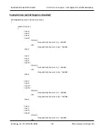
Register Map…
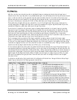
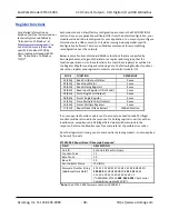
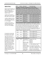
Note that this model provides two
different modes of register access
for its digital outputs, Coil
Registers or Holding Registers,
and only one mode may be
enabled at a time.
The table at right outlines the
Modbus register map for a Model
XT1531‐000 network I/O module.
The 0000x Coil Registers are only
applicable with the Support Coil
versus Holding registers option of
the module enabled.
The 40001 Holding Register is
only applicable with the Support
Coil versus Holding registers
option of the module disabled.
It is possible that a digital input
state indication may not reflect
the actual state of the tandem
output, if the I/O channel is
experiencing contention between
a field signal and its tandem
output that happens to be turned
ON. If simply monitoring field
input signals, the corresponding
tandem output must be turned
OFF to avoid this contention
between the local digital output
channel and a field signal tied to
its tandem input. If you
accidentally create contention, a
protection mechanism in the
output may be triggered and its
excitation will have to be cycled
OFF/ON to restore output
operation.
Ref.
Address Description
Data Type/Format
Coil Registers (0x References, Read/Write Discrete Outputs/Coils)
–
0000x Registers Are Only Applicable if Coil Registers Have Been Enabled.
The Modbus Force Single Coil or Force Multiple Coil command directed to this
address will drive the corresponding output to source excitation to the load (set
bit), or turn the output OFF (clear bit). The default state is clear (OFF) and outputs
do not float. The Invert Input Logic function does not affect this output logic. The
Modbus Read Coil Status command directed to these channels will return a data
byte with its lsb aligned to the starting address and unused bits are returned as 0.
0
0001
0000
Digital Output
Channel 0 State
A 16‐bit register that
addresses the
state to set the digital output to.
0
0002
0001
Digital Output
Channel 1 State
A 16‐bit register that addresses the
state to set the digital output to.
0
0003
0002
Digital Output
Channel 2 State
A 16‐bit register that addresses the
state to set the digital output to.
0
0004
0003
Digital Output
Channel 3 State
A 16‐bit register that addresses the
state to set the digital output to.
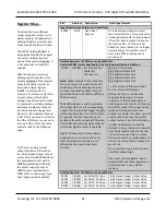
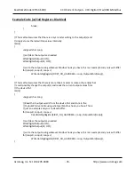
Contact or Input Status Registers (1x References, Read Only Discrete Inputs)
The Modbus Read Input Status command directed to these addresses will return
the state of the corresponding digital input relative to a TTL threshold. The lsb of
the returned data corresponds to the input channel number at the starting
address specified, with successive coils following sequentially. All digital I/O
channels are pulled‐down to return and do not float. Unused data bits are
returned as 0. A set bit (1) means the corresponding digital input is High or ON
(above 2V). A clear bit (0) means the input is Low or OFF (below 2V). Note that
digital I/O does not operate without excitation.
10001
0000
Digital Input CH 0
ON/OFF status
A 16‐bit register that addresses the
state of the digital input.
10002
0001
Digital Input CH 1
ON/OFF status
A
16‐bit register that addresses the
state of the digital input.
10003
0002
Digital Input CH 2
ON/OFF status
A 16‐bit register that addresses the
state of the digital input.
10004
0003
Digital Input CH 3
ON/OFF status
A 16‐bit register that
addresses the
state of the digital input.
Input Registers (3x References, Read‐Only)
3
0001
0000
DI Input State for
Digital I/O Channels
0‐3.
Note:
This register
reflects the actual
states of the
corresponding
digital input signals,
or the source states
of the tandem p‐
channel output
switches (signal is
active‐high).
Bit 15‐4
: 0 (Not Used)
Bit 3: CH3
Bit 2: CH2
Bit 1: CH1
Bit 0: CH0
1 = ON or High (Input Asserted > 2V)
0 = OFF or Low (Input < 0.8V)
A set bit (1) means input is ON or
asserted high. A clear bit (0) means
input is OFF or asserted low. Unused
bits are set to 0. This logic only
applies if the Input Logic Invert
function is set to “No” or disabled.