BusWorks Model XT1531‐000
4 CH Current 4 CH Digital I/O w/USB & Modbus
Acromag, Inc. Tel: 248‐295‐0880
‐
18
‐
Quick Overview…
HELP
–
You can press F1 for Help on a selected or highlighted field
or
control. You can also click the [?] button in the upper‐right
hand corner of the screen and then click to point to a field or
control to get a Help message pertaining to the item you pointed
to.
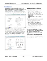
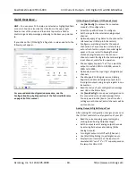
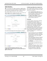
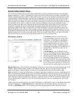
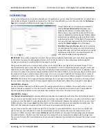
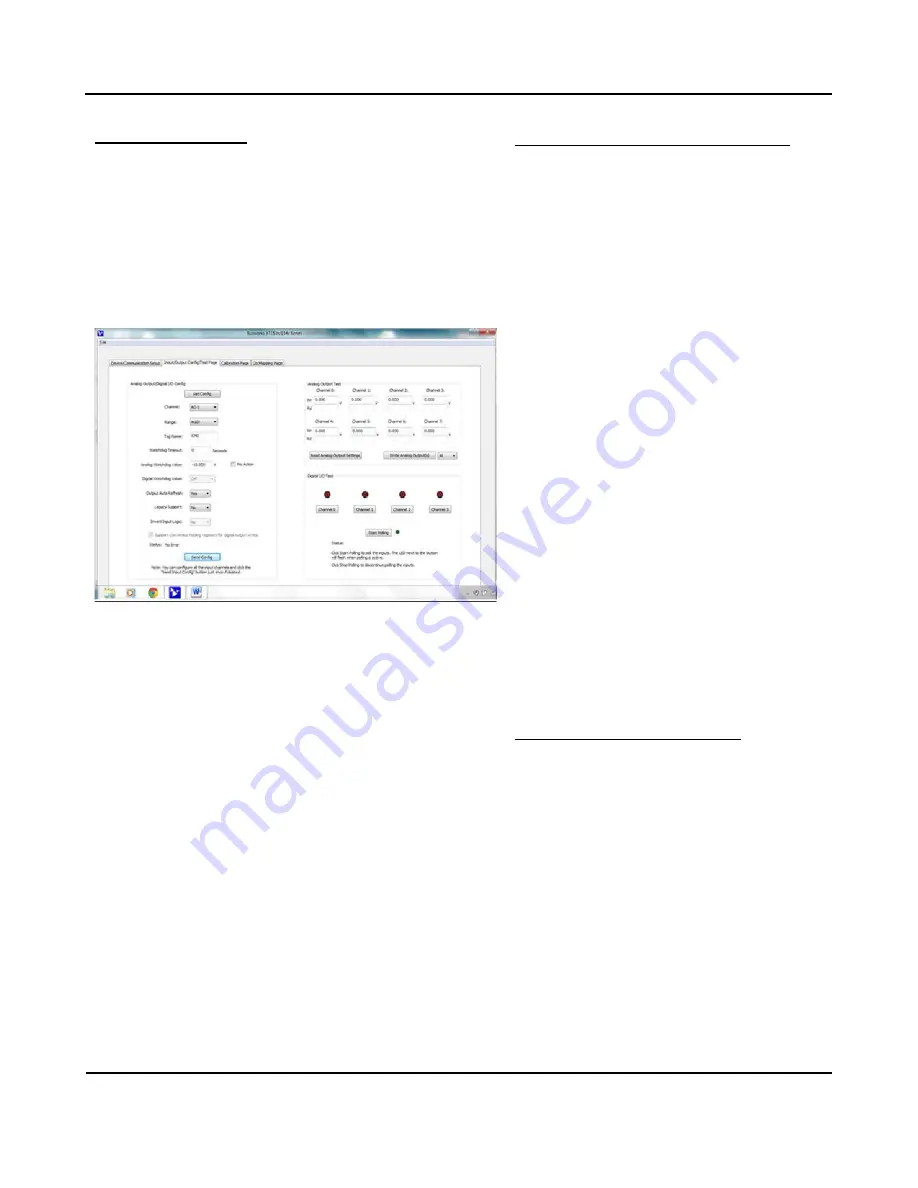
If you click on the I/O Config/Test Page tab, a screen similar to the
following will appear:
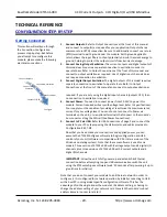
For a more detailed configuration procedure, see the
Configuration Step‐by‐Step section of the Technical Reference
on page 18 of this manual.
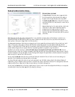
I/O Configure (Configure I/O Channels Here)
•
Use
[Get Config]
to retrieve the connected
module’s I/O
configuration.
•
Select the specific channel to configure.
•
Set the range for the selected analog output
channel.
•
Optionally apply a Tag Name to the channel for
reference over USB (up to 8 characters).
•
Configure a watchdog timer for the output
channel and a Timeout value or state. Setup
auto‐refresh for the outputs to combat digital
upset or force a restart following thermal
shutdown (digital outputs). You can even
choose to invert the logic for the tandem digital
input channel, useful for i2o operation.
•
Choose Legacy Support=”Yes” if you want
the
output to scale 0‐100% to 0‐20000, versus 0‐
100% to
0‐30000.
•
Optionally invert the Input Logic of digital input
channels.
•
Check Support Coil Register versus Holding
Register to enable write digital outputs to all
four digital outputs using a single register in one
transaction.
•
Read the status of your configuration message
over USB in the Status field.
•
Use
[Send Config]
to send your configuration to
the connected unit and read message Status.
You only need to click [Send…] one time after
setting up each channel, and all channels will be
written at once.
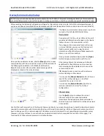
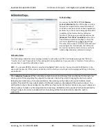
Analog Output & Digital Output Test
After making I/O configuration changes, you can use
the I/O Test controls to verify operation of your I/O.
•
Read the current analog output settings by
clicking [Read Analog Output Settings].
•
Set the output level of analog output channels
by entering field values and clicking [Write
Analog Outputs].
•
Turn digital outputs On/Off with
[Channel…].
•
Use [Start/Stop Polling] to poll digital inputs.
•
Display the current state of the inputs with
simulated LED’s and “1” or “0” superimposed on
the lamps for ON or OFF.


