BusWorks Model XT1531‐000
4 CH Current 4 CH Digital I/O w/USB & Modbus
Acromag, Inc. Tel: 248‐295‐0880
‐
19
‐
Quick Overview…
HELP
–
You can press F1 for Help on a selected or highlighted field
or control. You can also click the [?] button in the upper‐right hand
corner of the screen and then click to point to a field or control to
get a Help message pertaining to the item you pointed to.
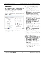
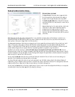
After configuring and/or testing your channels, you can click on the
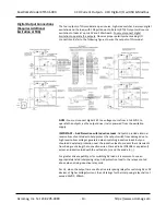
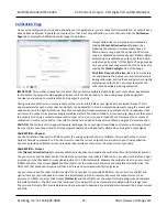
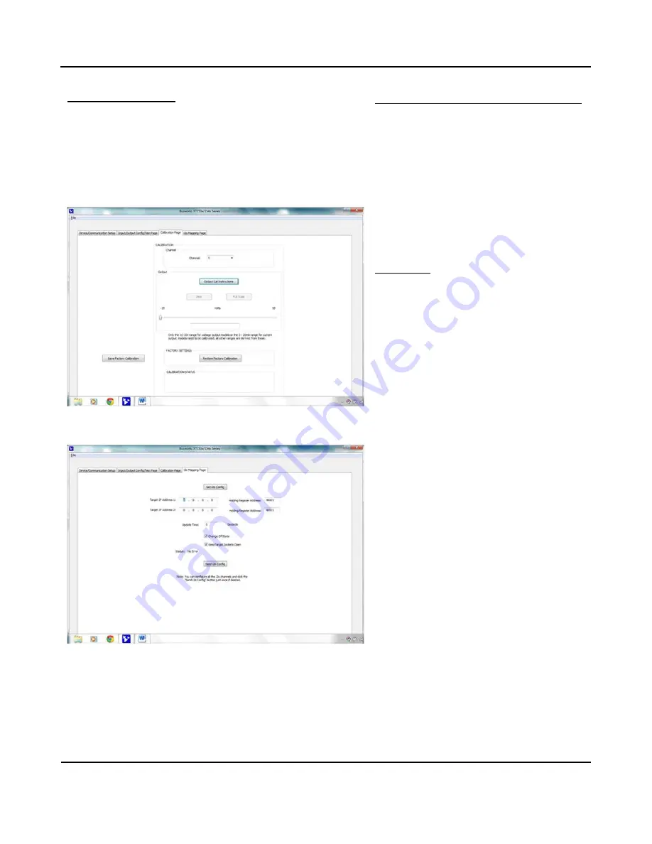
Output Calibration tab to display the following screen:
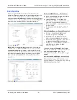
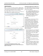
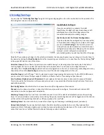
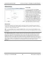
If you click the i2o Mapping tab, the following screen will appear:
For a more detailed configuration procedure, see the
Configuration
Step‐by‐Step section of the Technical Reference on
page 18 of this manual.
Calibration Page (Calibrate Your Outputs Here)
If your outputs exhibit excessive error, you can use
the controls of this page to calibrate each Voltage
Output channel separately.
•
Click the
[Output Cal Instructions]
button to
begin analog output calibration and follow the
on‐screen prompts to calibrate output Zero
and Full‐scale of the output
channel.
•
Use
[Zero]
and
[Full Scale]
and measure the
output range zero or full‐scale signal
and
enter the measured value here.
i2o Mapping
This model includes a special remote messaging
function called i2o, for input‐to‐output
communication with respect to its digital input
channels. This allows it to send its digital input
information over the network, to digital outputs
on another unit, or compatible unit, without
having to hard‐wire a connection. The i2o
Mapping Page shown at left is used to setup this
feature by specifying the IP address of the target
output module to send input channel data to,
either upon change‐of‐state, or cyclically at the
update time specified.
•
Set the IP address of one or two target digital
output devices (XT1111, XT1121, or XT1531
XT1541 modules) to send this modules digital
input data (four channels) to their digital
output channels.
•
Set the Holding Register address of the group
of 4 output channels at an XT1111, XT1121,
XT1531, or XT1541 output module that you
are targeting to send the digital input data of
this module to.
•
Set an Update Time to cyclically send this
module’s digital input states every interval
of
update time.
•
Specify to send data upon change of state, or
cyclically per an update rate that you specify.
•
Retrieve the current i2o configuration from
the connected module, or send a new
configuration to the connected module.


