BusWorks Model XT1531‐000
4 CH Current 4 CH Digital I/O w/USB & Modbus
Acromag, Inc. Tel: 248‐295‐0880
‐
37
‐
Domain Name System (DNS)
DNS denotes the Domain Name System or Domain Name Server and refers to the
system used to associate an alphanumeric character string with a numeric IP
address. The DNS is actually a distributed database of domain names and
corresponding IP addresses. These servers contain information on some segment of
the domain name space and make this information available to clients called
resolvers
. For example, the DNS allows us to use “Acromag.com” as an IP address
rather than a more complicated number string.
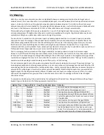
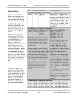
MODBUS REGISTERS
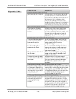
Modbus registers are typically organized into different reference types identified by
the leading number of the reference address:
Reference
Description
0xxxx
Read/Write Discrete Outputs or Coils. A 0x reference address is
used to drive output data to a digital output channel.
1xxxx
Read Discrete Inputs. The ON/OFF status of a 1x reference
address is controlled by the corresponding digital input
channel.
3xxxx
Read Input Registers
. A 3x reference register contains a 16‐bit
number received from an external source
—
e.g. an analog
signal or a group of digital channels.
4xxxx
Read/Write Output or Holding Register. A 4x register is used to
store
16‐bits of numerical data (binary or decimal), or to send
the data from the CPU to output channel(s).
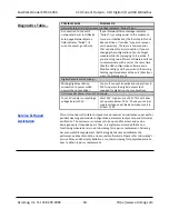
The “Reference” leading character indicated above is generally implied by the
function code and omitted from the address specifier for a given function. The
leading character also identifies the I/O data type. The “x” following the leading
character represents a four‐digit address location in user data memory.
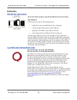
No configuration is possible over the network for this model, as it uses a USB
connection to configure its operation instead.
DIO models will typically denote the ON/OFF state of discrete inputs and/or outputs
using a 1 or 0 value assigned to an individual bit of a 16‐bit data word. Modbus
allows sixteen 0x or 1x references per data word. With respect to mapping, the LSB
of the word maps to the lowest numbered channel of a group and channel numbers
increase sequentially as you move towards the MSB. Unused bit positions are
usually set to zero.
I/O values are accessed via the 16‐bit Input Registers or 16‐bit Holding Registers
given in the Register Map. Input registers contain information that is read‐only. For
example, the current input value read from a channel, or the states of a group of
digital inputs. Holding registers contain read/write information that may be
configuration data or output data. For example, the high limit value of an alarm
function operating at an input, or an output value for an output channel.

