BusWorks Model XT1531‐000
4 CH Current 4 CH Digital I/O w/USB & Modbus
Acromag, Inc. Tel: 248‐295‐0880
‐
14
‐
Digital Input Connections
(Does Not Require
Additional Excitation)
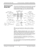
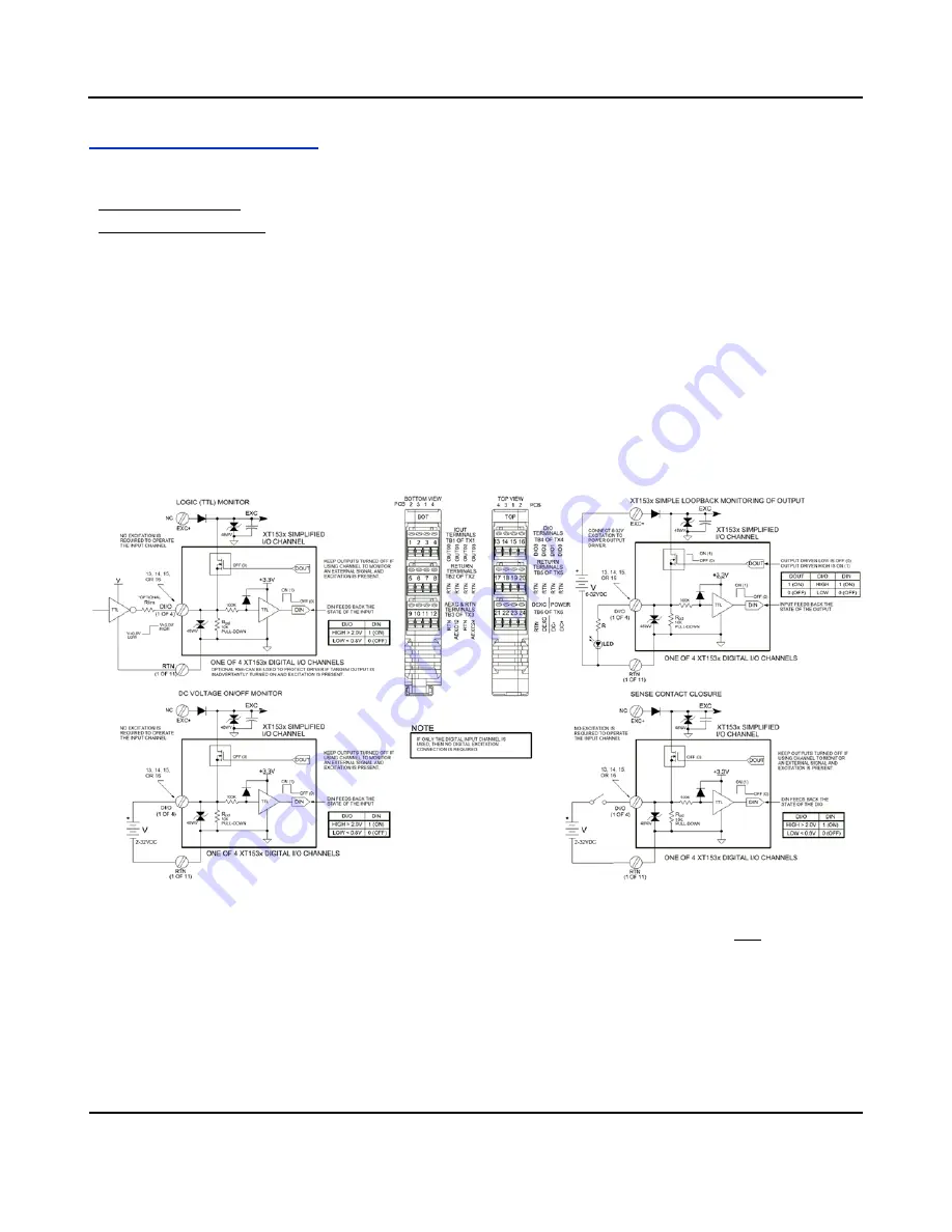
The four active‐high inputs of this model are already wired to accomplish loopback
monitoring of the open‐source, high‐side switch outputs, but may alternately be
used to monitor input levels from the field when their tandem outputs are switched
OFF. Inputs of this model accept voltage signals up to 32V, are active‐high, and use
TTL thresholds for logic transfer. They additionally are pulled down to Return via
10K pull‐down resistors installed on the board and will never floa
t. Observe proper
polarity when making I/O connections. Refer to the following figures to wire the
digital inputs of this model.
IMPORTANT:
You must keep the tandem output turned off when using the input to
sense voltage levels from the field to prevent contention between the field signal
and the output channel, which may be turned ON. If you inadvertently cause
contention, it can trigger the output’s protection mechanism to shut it down. In this
instance, you would have to cycle excitation OFF/ON to restore operation of the
digital output.
NOTE:
You do not need to connect digital excitation if you are only using the digital
input channels to monitor field inputs. Digital excitation is only required to operate
the tandem sourcing digital outputs.


