


System Utilities
2-11
2.
Type current password in
Enter Current Password
field and press
Enter
.
3.
Press
Enter
twice
without
typing anything in
Enter New Password
and
Confirm New
Password
fields. Computer will set
Supervisor Password
parameter to
Clear
.
4.
Press
F10
to save changes and exit the
BIOS Setup Utility
.
Changing a Password
0
1.
Use the
and
keys to highlight
Set Supervisor Password
and press
Enter
. The
Set Supervisor Password
dialog is shown. (Figure 2-9)
Figure 2-9.
Changing a Password: Set Supervisor Password
2.
Type current password in
Enter Current Password
field and press
Enter
.
3.
Type new password in
Enter New Password
field and press
Enter
.
4.
Retype new password in
Confirm New Password
field and press
Enter
.
5.
If new password and confirm new password strings match, The
Setup Notice
dialog is
shown (Figure 2-10). If it is not shown, go to step 6.
Figure 2-10.
Changing a Password: Setup Notice
a.
Press
Enter
to return to the
BIOS Setup Utility Security
menu.
b.
The Supervisor Password
parameter is shown as
Set.
c.
Press
F10
to save changes and exit
BIOS Setup Utility
.
6.
If current password and new password strings do not match, the
Setup Warning
dialog
is shown (Figure 2-11). If it is not shown, go to step 7.
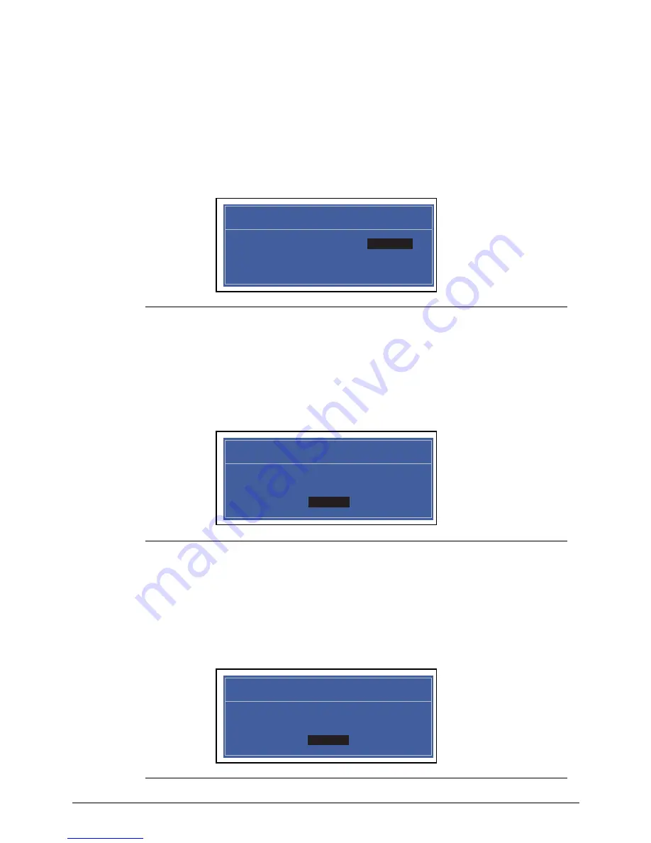
Figure 2-11.
Changing a Password: Invalid Password
Set Supervisor Password
Enter Current Password [ ]
Enter Current Password
Enter New Password [ ]
Confirm New Password [ ]
Setup Notice
Changes have been saved.
[Continue]
Continue
Setup Warning
Invalid Password.
[Continue]
Continue
Summary of Contents for Aspire Z1100
Page 1: ...i SERVICE GUIDE Aspire Z1100 ...
Page 10: ...x ...
Page 11: ...CHAPTER 1 Hardware Specifications ...
Page 14: ...1 4 ...
Page 42: ...1 32 Hardware Specifications and Configurations ...
Page 43: ...Hardware Specifications and Configurations 1 33 ...
Page 44: ...1 34 Hardware Specifications and Configurations ...
Page 45: ...CHAPTER 2 System Utilities ...
Page 70: ...2 26 System Utilities ...
Page 71: ...CHAPTER 3 Machine Maintenance Procedures ...
Page 74: ...3 4 ...
Page 126: ...3 56 Machine Maintenance Procedures ...
Page 127: ...CHAPTER 4 Troubleshooting ...
Page 149: ...CHAPTER 5 Jumper and Connector Locations ...
Page 156: ...5 8 Jumper and Connector Locations ...
Page 157: ...CHAPTER 6 FRU Field Replaceable Unit List ...
Page 158: ...6 2 Exploded Diagrams 6 4 Main Assembly 6 4 FRU List 6 6 Screw List 6 13 ...
Page 170: ...6 14 FRU Field Replaceable Unit List ...
Page 171: ...CHAPTER 7 Online Support Information ...
Page 172: ...7 2 Introduction 7 3 ...
Page 174: ...7 4 Online Support Information ...


