


Chapter 1
21
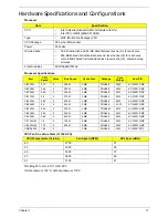
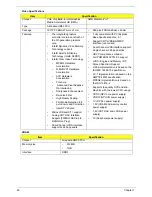
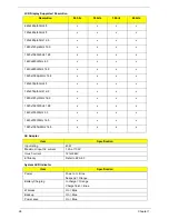
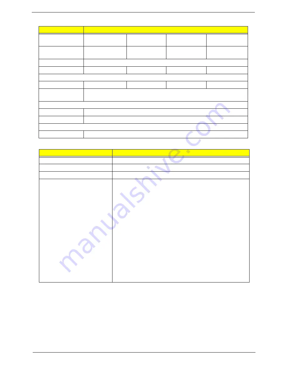
Hard Disk Drive Interface
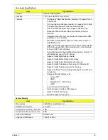
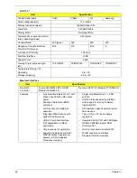
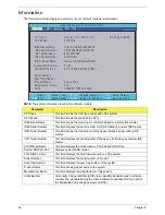
BIOS
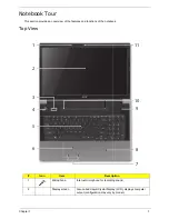
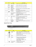
Item
Specification
Vendor & Model
Name
Seagate
HGST
Toshiba
Western Digital
Capacity (GB)
160, 250, 320,
500
160, 250, 320,
500
160, 250, 320,
500
160, 250, 320,
500, 640
Bytes per sector
512
Data heads
4,3,2,2
2,2,3,3
1,3,2,3
1,2,2,4,4
Drive Format
Disks
1,1,1,2,2
1,1,2,2
1,2,1,2
1,1,1,2,2
Spindle speed
(RPM)
5400
Performance Specifications
Buffer size
8 MB
Interface
SATA
DC Power Requirements
Voltage tolerance
5V ±5%
Item
Specification
BIOS vendor
Phoenix
BIOS version
Release 4.0
BIOS ROM type
Flash
Features
•
Flash ROM 4MB
•
Support ISIPP
•
Support Acer UI
•
Support multi-boot
•
Suspend to RAM (S3)/Disk (S4)
•
Various hot-keys for system control
•
Support SMBIOS 2.3, PCI2.2.
•
Refer to Acer BIOS specification.
•
DMI utility for BIOS serial number configurable/asset tag
•
Support PXE
•
Support Y2K solution
•
Support WinFlash
•
Wake on LAN from S3
•
Wake on LAN form S4 in AC mode
•
System information
Summary of Contents for ASPIRE 7745
Page 6: ...VI ...
Page 10: ...X Table of Contents ...
Page 40: ...30 Chapter 1 ...
Page 56: ...46 Chapter 2 ...
Page 68: ...58 Chapter 3 5 Pull the WLAN module out and away ...
Page 73: ...Chapter 3 63 5 Remove the ODD bracket 6 Pry the ODD bezel off of the ODD module ...
Page 83: ...Chapter 3 73 5 Detach the Bluetooth module cable from the module ...
Page 91: ...Chapter 3 81 4 Lift the thermal module away from the main board ...
Page 96: ...86 Chapter 3 4 Unlock and disconnect the switch board FFC ...
Page 101: ...Chapter 3 91 4 Remove the bezel from the LCD module ...
Page 108: ...98 Chapter 3 5 Pry the right antenna from the casing ...
Page 111: ...Chapter 3 101 3 Lay the cables around the module edge ...
Page 115: ...Chapter 3 105 10 Place the LVDS cable into cable guides ...
Page 118: ...108 Chapter 3 4 Replace the two 2 bezel screws ...
Page 129: ...Chapter 3 119 4 Connect the Bluetooth module cable to the main board ...
Page 136: ...126 Chapter 3 6 Connect and lock the Power board FFC ...
Page 143: ...Chapter 3 133 4 Grasp the tab and slide the HDD firmly into the docking connector ...
Page 145: ...Chapter 3 135 4 Push the ODD completely into the bay until flush with the lower cover ...
Page 148: ...138 Chapter 3 ...
Page 166: ...156 Chapter 4 ...
Page 288: ...278 Appendix B ...
Page 290: ...280 ...


