


Chapter 4
139
Troubleshooting
Common Problems
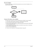
Use the following procedure as a guide for computer problems.
NOTE:
The diagnostic tests are intended to test only Acer products. Non-Acer products, prototype cards, or
modified options can give false errors and invalid system responses.
1.
Obtain the failing symptoms in as much detail as possible.
2.
Verify the symptoms by attempting to re-create the failure by running the diagnostic test or by repeating
the same operation.
3.
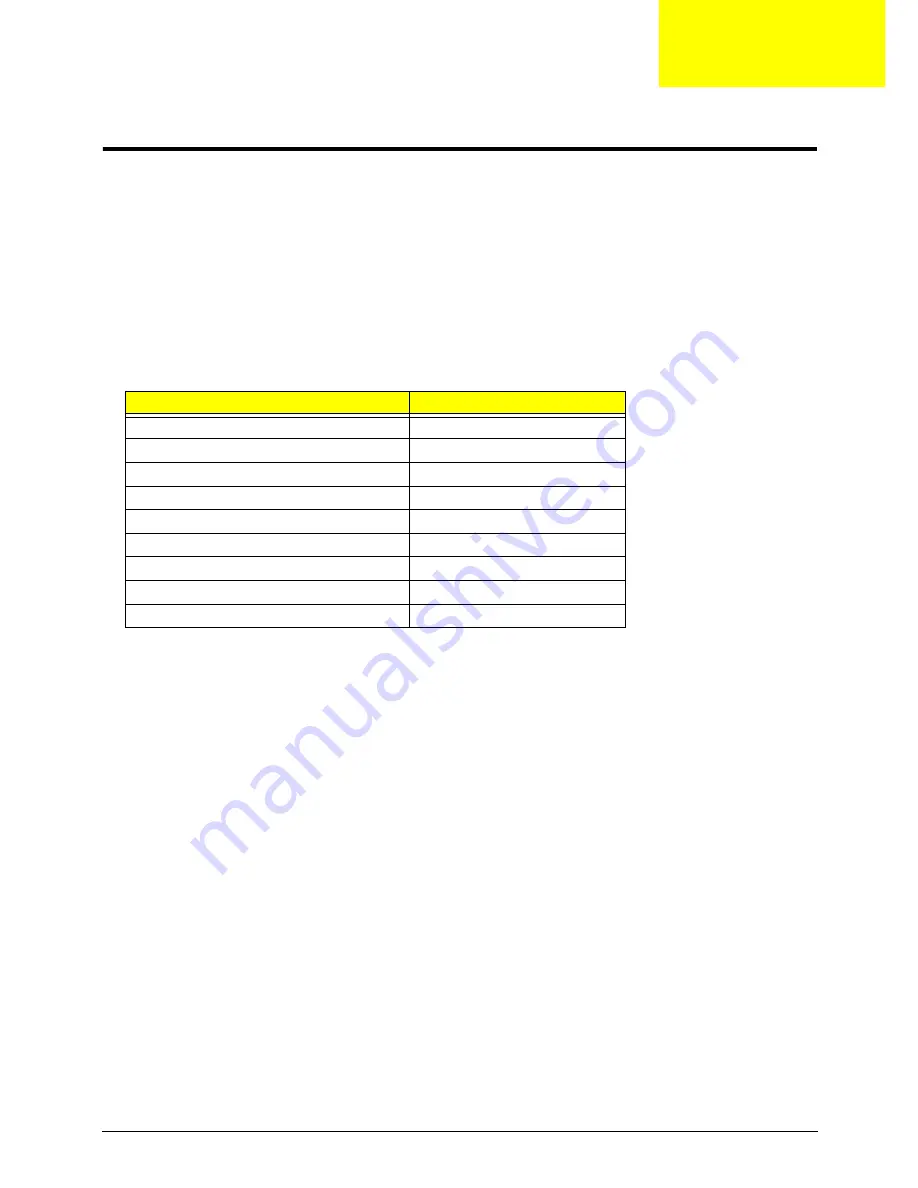
Use the following table with the verified symptom to determine which page to go to.
4.
If the Issue is still not resolved, see “Online Support Information” on page 279.
Symptoms (Verified)
Go To
Power On Issue
Page 140
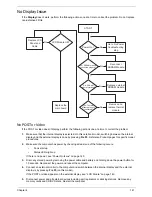
No Display Issue
Page 141
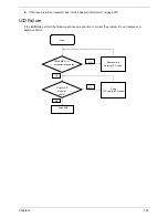
LCD Failure
Page 143
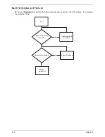
Internal Keyboard Failure
Page 144
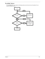
TouchPad Failure
Page 145
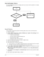
Internal Speaker Failure
Page 146
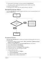
Internal Microphone Failure
Page 147
USB Failure
Page 149
Other Function Failure
Page 149
Chapter 4
Summary of Contents for ASPIRE 7745
Page 6: ...VI ...
Page 10: ...X Table of Contents ...
Page 40: ...30 Chapter 1 ...
Page 56: ...46 Chapter 2 ...
Page 68: ...58 Chapter 3 5 Pull the WLAN module out and away ...
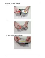
Page 73: ...Chapter 3 63 5 Remove the ODD bracket 6 Pry the ODD bezel off of the ODD module ...
Page 83: ...Chapter 3 73 5 Detach the Bluetooth module cable from the module ...
Page 91: ...Chapter 3 81 4 Lift the thermal module away from the main board ...
Page 96: ...86 Chapter 3 4 Unlock and disconnect the switch board FFC ...
Page 101: ...Chapter 3 91 4 Remove the bezel from the LCD module ...
Page 108: ...98 Chapter 3 5 Pry the right antenna from the casing ...
Page 111: ...Chapter 3 101 3 Lay the cables around the module edge ...
Page 115: ...Chapter 3 105 10 Place the LVDS cable into cable guides ...
Page 118: ...108 Chapter 3 4 Replace the two 2 bezel screws ...
Page 129: ...Chapter 3 119 4 Connect the Bluetooth module cable to the main board ...
Page 136: ...126 Chapter 3 6 Connect and lock the Power board FFC ...
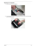
Page 143: ...Chapter 3 133 4 Grasp the tab and slide the HDD firmly into the docking connector ...
Page 145: ...Chapter 3 135 4 Push the ODD completely into the bay until flush with the lower cover ...
Page 148: ...138 Chapter 3 ...
Page 166: ...156 Chapter 4 ...
Page 288: ...278 Appendix B ...
Page 290: ...280 ...


