


150
Chapter 4
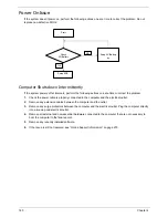
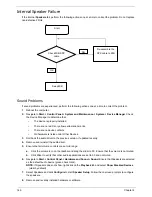
Intermittent Problems
Intermittent system hang problems can be caused by a variety of reasons that have nothing to do with a
hardware defect, such as: cosmic radiation, electrostatic discharge, or software errors. FRU replacement
should be considered only when a recurring problem exists.
When analyzing an intermittent problem, do the following:
1.
Run the advanced diagnostic test for the system board in loop mode at least 10 times.
2.
If no error is detected, do not replace any FRU.
3.
If any error is detected, replace the FRU. Rerun the test to verify that there are no more errors.
Undetermined Problems
The diagnostic problems does not identify which adapter or device failed, which installed devices are incorrect,
whether a short circuit is suspected, or whether the system is inoperative.
Follow these procedures to isolate the failing FRU (do not isolate non-defective FRU).
NOTE:
Verify that all attached devices are supported by the computer.
NOTE:
Verify that the power supply being used at the time of the failure is operating correctly. (See “Power On
Issue” on page 140.):
1.
Power-off the computer.
2.
Visually check them for damage. If any problems are found, replace the FRU.
3.
Remove or disconnect all of the following devices:
•
Non-Acer devices
•
Printer, mouse, and other external devices
•
Battery pack
•
Hard disk drive
•
DIMM
•
CD-ROM/Diskette drive Module
•
PC Cards
4.
Power-on the computer.
5.
Determine if the problem has changed.
6.
If the problem does not recur, reconnect the removed devices one at a time until you find the failing FRU.
7.
If the problem remains, replace the following FRU one at a time. Do not replace a non-defective FRU:
•
System board
•
LCD assembly
Summary of Contents for ASPIRE 7745
Page 6: ...VI ...
Page 10: ...X Table of Contents ...
Page 40: ...30 Chapter 1 ...
Page 56: ...46 Chapter 2 ...
Page 68: ...58 Chapter 3 5 Pull the WLAN module out and away ...
Page 73: ...Chapter 3 63 5 Remove the ODD bracket 6 Pry the ODD bezel off of the ODD module ...
Page 83: ...Chapter 3 73 5 Detach the Bluetooth module cable from the module ...
Page 91: ...Chapter 3 81 4 Lift the thermal module away from the main board ...
Page 96: ...86 Chapter 3 4 Unlock and disconnect the switch board FFC ...
Page 101: ...Chapter 3 91 4 Remove the bezel from the LCD module ...
Page 108: ...98 Chapter 3 5 Pry the right antenna from the casing ...
Page 111: ...Chapter 3 101 3 Lay the cables around the module edge ...
Page 115: ...Chapter 3 105 10 Place the LVDS cable into cable guides ...
Page 118: ...108 Chapter 3 4 Replace the two 2 bezel screws ...
Page 129: ...Chapter 3 119 4 Connect the Bluetooth module cable to the main board ...
Page 136: ...126 Chapter 3 6 Connect and lock the Power board FFC ...
Page 143: ...Chapter 3 133 4 Grasp the tab and slide the HDD firmly into the docking connector ...
Page 145: ...Chapter 3 135 4 Push the ODD completely into the bay until flush with the lower cover ...
Page 148: ...138 Chapter 3 ...
Page 166: ...156 Chapter 4 ...
Page 288: ...278 Appendix B ...
Page 290: ...280 ...


