


Chapter 4
141
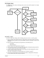
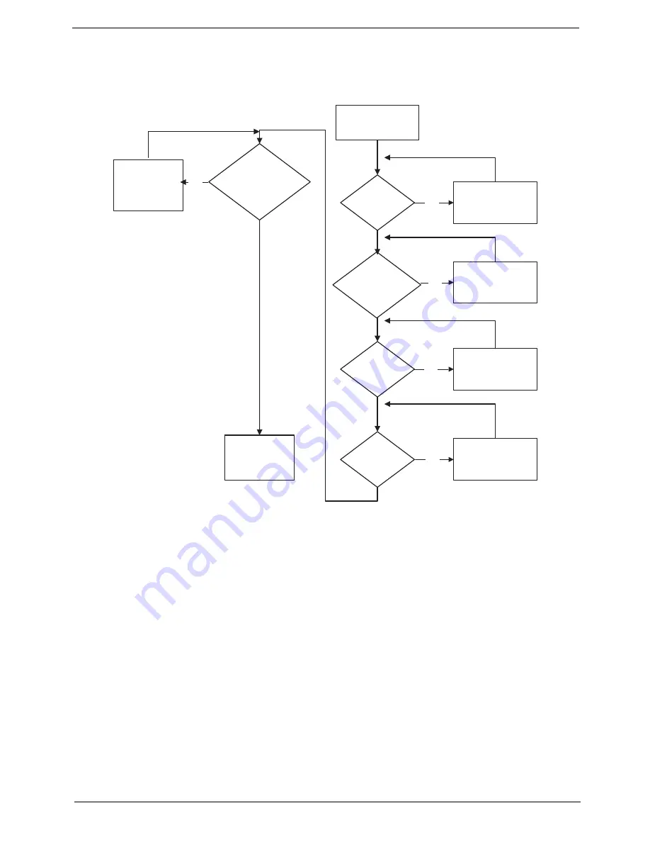
No Display Issue
If the
Display
doesn’t work, perform the following actions one at a time to correct the problem. Do not replace
non-defective FRUs:
No POST or Video
If the POST or video doesn’t display, perform the following actions one at a time to correct the problem.
1.
Make sure that the internal display is selected. On this notebook model, switching between the internal
display and the external display is done by pressing
Fn+F5
. Reference Product pages for specific model
procedures.
2.
Make sure the computer has power by checking at least one of the following occurs:
•
Fans start up
•
Status LEDs light up
If there is no power, see “Power On Issue” on page 140.
3.
Drain any stored power by removing the power cable and battery and holding down the power button for
10 seconds. Reconnect the power and reboot the computer.
4.
Connect an external monitor to the computer and switch between the internal display and the external
display is by pressing
Fn+F5
(on this model).
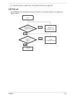
If the POST or video appears on the external display, see “LCD Failure” on page 143.
5.
Disconnect power and all external devices including port replicators or docking stations. Remove any
memory cards and CD/DVD discs. Restart the computer.
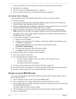
START
Power On ?
No
Go to No Power
troubleshooting
step
Replace external
DDRAM module
Remove and
replace thermal
module
Replace the
main board
Reconnect
SDRAM Module
LCD Module OK?
Replace LCD
Panel and
Cable
Ext. DDRAM module
connected properly?
Ext. DDRAM
module functional?
CPU Thermal
Module properly
connected?
No
No
No
No
Summary of Contents for ASPIRE 7745
Page 6: ...VI ...
Page 10: ...X Table of Contents ...
Page 40: ...30 Chapter 1 ...
Page 56: ...46 Chapter 2 ...
Page 68: ...58 Chapter 3 5 Pull the WLAN module out and away ...
Page 73: ...Chapter 3 63 5 Remove the ODD bracket 6 Pry the ODD bezel off of the ODD module ...
Page 83: ...Chapter 3 73 5 Detach the Bluetooth module cable from the module ...
Page 91: ...Chapter 3 81 4 Lift the thermal module away from the main board ...
Page 96: ...86 Chapter 3 4 Unlock and disconnect the switch board FFC ...
Page 101: ...Chapter 3 91 4 Remove the bezel from the LCD module ...
Page 108: ...98 Chapter 3 5 Pry the right antenna from the casing ...
Page 111: ...Chapter 3 101 3 Lay the cables around the module edge ...
Page 115: ...Chapter 3 105 10 Place the LVDS cable into cable guides ...
Page 118: ...108 Chapter 3 4 Replace the two 2 bezel screws ...
Page 129: ...Chapter 3 119 4 Connect the Bluetooth module cable to the main board ...
Page 136: ...126 Chapter 3 6 Connect and lock the Power board FFC ...
Page 143: ...Chapter 3 133 4 Grasp the tab and slide the HDD firmly into the docking connector ...
Page 145: ...Chapter 3 135 4 Push the ODD completely into the bay until flush with the lower cover ...
Page 148: ...138 Chapter 3 ...
Page 166: ...156 Chapter 4 ...
Page 288: ...278 Appendix B ...
Page 290: ...280 ...


