


270
Appendix A
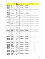
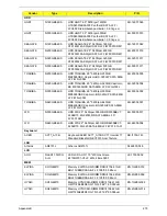
AS7745-
431G32Mi
WW
WW
S2.PTZ0
2.004
AS7745-431G32Mi W7HP64AWW1 MC
UMACks_3V3J 1*1G/320/BT/6L2.2/5R/
CB_bg_1.3C_GEk_ES62
AS7745-
332G57Bn
WW
WW
S2.PTZ0
2.007
AS7745-332G57Bn W7HP64AWW1 MC
UMACks_3V3J 2*1G/250+320/BT/6L2.2/5R/
CB_bgn_1.3C_GEk_ES62
AS7745-
332G57Bn
WW
WW
S2.PTZ0
2.007
AS7745-332G57Bn W7HP64AWW1 MC
UMACks_3V3J 2*1G/250+320/BT/6L2.2/5R/
CB_bgn_1.3C_GEk_ES62
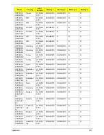
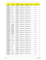
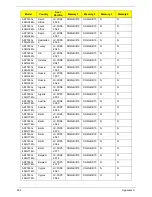
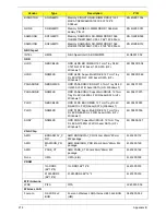
Model
RO
Country
Acer Part No
BOM Name
CPU
AS7745-
434G50Mn
EMEA
UK
LX.PTZ02.001
AS7745_UMACks_3J
Ci5430M
AS7745-
432G48Mi
WW
GCTWN
S2.PTZ02.005
AS7745_UMACks_3J
Ci5430M
AS7745-
432G48Mi
WW
GCTWN
S2.PTZ02.005
AS7745_UMACks_3J
Ci5430M
AS7745-
432G48Mi
WW
WW
S2.PTZ02.006
AS7745_UMACks_3J
Ci5430M
AS7745-
432G48Mi
WW
WW
S2.PTZ02.006
AS7745_UMACks_3J
Ci5430M
AS7745-
431G48Mn
WW
GCTWN
S2.PTZ02.001
AS7745_UMACks_3J
Ci5430M
AS7745-
431G48Mn
WW
GCTWN
S2.PTZ02.001
AS7745_UMACks_3J
Ci5430M
AS7745-
431G48Mn
WW
WW
S2.PTZ02.002
AS7745_UMACks_3J
Ci5430M
AS7745-
431G48Mn
WW
WW
S2.PTZ02.002
AS7745_UMACks_3J
Ci5430M
AS7745-
431G32Mi
WW
GCTWN
S2.PTZ02.003
AS7745_UMACks_3J
Ci5430M
AS7745-
431G32Mi
WW
GCTWN
S2.PTZ02.003
AS7745_UMACks_3J
Ci5430M
AS7745-
431G32Mi
WW
WW
S2.PTZ02.004
AS7745_UMACks_3J
Ci5430M
AS7745-
431G32Mi
WW
WW
S2.PTZ02.004
AS7745_UMACks_3J
Ci5430M
AS7745-
332G57Bn
WW
WW
S2.PTZ02.007
AS7745_UMACks_3J
Ci3330M
AS7745-
332G57Bn
WW
WW
S2.PTZ02.007
AS7745_UMACks_3J
Ci3330M
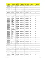
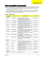
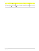
Model
RO
Country
Acer
Part No
VGA Chip
VRAM
1
HDD
1(GB)
HDD
2(GB)
AS7745-
434G50Mn
EMEA
UK
LX.PTZ
02.001
UMA
N
N500GB5.
4KS
N
AS7745-
432G48Mi
WW
GCTWN
S2.PTZ
02.005
UMA
N
N320GB5.
4KS
N160GB5.
4KS
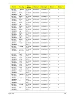
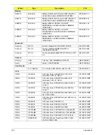
Model
RO
Country
Acer
Part No
Description
Summary of Contents for ASPIRE 7745
Page 6: ...VI ...
Page 10: ...X Table of Contents ...
Page 40: ...30 Chapter 1 ...
Page 56: ...46 Chapter 2 ...
Page 68: ...58 Chapter 3 5 Pull the WLAN module out and away ...
Page 73: ...Chapter 3 63 5 Remove the ODD bracket 6 Pry the ODD bezel off of the ODD module ...
Page 83: ...Chapter 3 73 5 Detach the Bluetooth module cable from the module ...
Page 91: ...Chapter 3 81 4 Lift the thermal module away from the main board ...
Page 96: ...86 Chapter 3 4 Unlock and disconnect the switch board FFC ...
Page 101: ...Chapter 3 91 4 Remove the bezel from the LCD module ...
Page 108: ...98 Chapter 3 5 Pry the right antenna from the casing ...
Page 111: ...Chapter 3 101 3 Lay the cables around the module edge ...
Page 115: ...Chapter 3 105 10 Place the LVDS cable into cable guides ...
Page 118: ...108 Chapter 3 4 Replace the two 2 bezel screws ...
Page 129: ...Chapter 3 119 4 Connect the Bluetooth module cable to the main board ...
Page 136: ...126 Chapter 3 6 Connect and lock the Power board FFC ...
Page 143: ...Chapter 3 133 4 Grasp the tab and slide the HDD firmly into the docking connector ...
Page 145: ...Chapter 3 135 4 Push the ODD completely into the bay until flush with the lower cover ...
Page 148: ...138 Chapter 3 ...
Page 166: ...156 Chapter 4 ...
Page 288: ...278 Appendix B ...
Page 290: ...280 ...


