


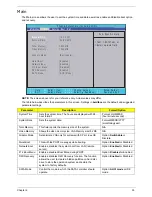


20
Chapter 1
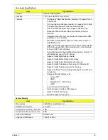
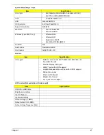
Video Specifications
VRAM
Item
Specification
Chipset
VGA chip Build-in Intel Graphics
Media Accelerator HD (UMA)
AMD Madison-Pro
*
Type
Arrandale HM55 PCH
Package
1071P FCBGA 27mm x 27mm
•
962-pins FCBGA 29mm x 29mm
Features
•
The integrated graphics
controller contains a refresh of
the 5th generation graphics
core.
•
Intel® Dynamic Video Memory
Technology support
•
Intel® Smart 2D Display
Technology (Intel® S2DDT)
•
Intel® Clear Video Technology
•
MPEG2 Hardware
Acceleration
•
WMV9/VC1 Hardware
Acceleration
•
AVC Hardware
Acceleration
•
ProcAmp
•
Advanced Pixel Adaptive
De-interlacing
•
Sharpness Enhancement
•
De-noise Filter
•
High Quality Scaling
•
Film Mode Detection (3:2
pull -down) and Correction
•
Intel® TV Wizard
•
Microsoft DirectX*11 support
•
Analog CRT DAC Interface
Support (300MHz DAC/up to
QXGA/Hot -Plug)
•
Dual-Channel LVDS interface
support 2x24 bpp panels
•
Fully compliant with PCI Express
Base Specification Rev. 2.1
•
Support CRT/LVDS/HDMI/DP
interface (concurrent)
•
Dual-channel LVDS interface support:
single channel 24 bpp dual link
•
HDCP compliance embed-in
•
Full POWERPLAYTM 8.0 support
•
LVDS / Engine and Memory / DP
Spread Spectrum Support
•
H.264 implementation is based on the
ISO/IEC 14496-10 specification.
•
VC-1 implementation is based on the
SMPTE 421M specification.
•
MPEG2 implementation is based on
the ISO 13818 -2
•
Supports top quality DVD and Blu -
Ray disc with the lowest CPU usage.
•
VDDC (GPU core power supply)
•
VDDCI (GPU I/O power supply)
•
1V (DP PLL power supply)
•
1.5V (VRAM and memory control
power supply)
•
1.8V (CRT DAC and LVDS power
supply)
•
3V (Peripheral power supply)
Item
Specification
Chipset
Arrandale HM55 PCH
Memory size
•
512 MB
•
1 GB
Interface
DDR3
Summary of Contents for ASPIRE 7745
Page 6: ...VI ...
Page 10: ...X Table of Contents ...
Page 40: ...30 Chapter 1 ...
Page 56: ...46 Chapter 2 ...
Page 68: ...58 Chapter 3 5 Pull the WLAN module out and away ...
Page 73: ...Chapter 3 63 5 Remove the ODD bracket 6 Pry the ODD bezel off of the ODD module ...
Page 83: ...Chapter 3 73 5 Detach the Bluetooth module cable from the module ...
Page 91: ...Chapter 3 81 4 Lift the thermal module away from the main board ...
Page 96: ...86 Chapter 3 4 Unlock and disconnect the switch board FFC ...
Page 101: ...Chapter 3 91 4 Remove the bezel from the LCD module ...
Page 108: ...98 Chapter 3 5 Pry the right antenna from the casing ...
Page 111: ...Chapter 3 101 3 Lay the cables around the module edge ...
Page 115: ...Chapter 3 105 10 Place the LVDS cable into cable guides ...
Page 118: ...108 Chapter 3 4 Replace the two 2 bezel screws ...
Page 129: ...Chapter 3 119 4 Connect the Bluetooth module cable to the main board ...
Page 136: ...126 Chapter 3 6 Connect and lock the Power board FFC ...
Page 143: ...Chapter 3 133 4 Grasp the tab and slide the HDD firmly into the docking connector ...
Page 145: ...Chapter 3 135 4 Push the ODD completely into the bay until flush with the lower cover ...
Page 148: ...138 Chapter 3 ...
Page 166: ...156 Chapter 4 ...
Page 288: ...278 Appendix B ...
Page 290: ...280 ...