


Chapter 1
9
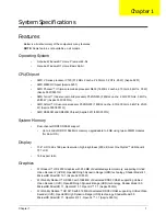
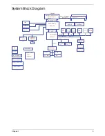
Bottom View
Indicators
The computer has several easy-to-read status indicators.
No.
Icon
Item
Description
1
Battery bay
Houses the computer's battery pack.
2
Battery release
latch
Releases the battery for removal.
3
Hard disk bay
Houses the computer's hard disk (secured
with screws).
4
Memory
compartment
Houses the computer's main memory.
5
Battery lock
Locks the battery in position.
6
Ventilation slots
and cooling fan
Enable the computer to stay cool, even after
prolonged use.
Note
: Do not cover or obstruct the fan opening.
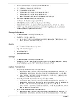
Icon
Function
Description
Power
Indicates the computer's power status.
Battery
Indicates the computer's battery status.
NOTE:
1.
Charging:
The light shows amber when
the battery is charging. 2.
Fully charged:
The light
shows green when in AC mode.
HDD
Indicates when the hard disk drive is active.
Communication indicator
Indicates the computer’s wireless connectivitoy
device status.
Summary of Contents for ASPIRE 5251
Page 6: ...VI...
Page 10: ...X Table of Contents...
Page 34: ...24 Chapter 1...
Page 52: ...42 Chapter 2...
Page 76: ...66 Chapter 3 5 Lift the Speaker clear of the Upper Cover...
Page 78: ...68 Chapter 3 5 Lift the Right Speaker Module clear of the device...
Page 84: ...74 Chapter 3 5 Lift the USB board clear of the device...
Page 90: ...80 Chapter 3 11 Disconnect the Bluetooth to mainboard cable...
Page 92: ...82 Chapter 3 4 Carefully lift the Thermal Module clear of the Mainboard...
Page 103: ...Chapter 3 93 7 Disconnect the LVDS cable from the panel...
Page 105: ...Chapter 3 95 5 Lift the microphone set and cable clear of the LCD cover...
Page 121: ...Chapter 3 111 5 Connect the fan cable...
Page 124: ...114 Chapter 3 6 Connect the LVDS cable to the mainboard 7 Connect the microphone cable...
Page 127: ...Chapter 3 117 4 Connect the USB cable to the mainboard and lock the connector...
Page 130: ...120 Chapter 3 4 Replace the FFC and press down as indicated to secure it to the Upper Cover...
Page 146: ...136 Chapter 3...
Page 175: ...Chapter 6 165 Aspire 5251 5551G 5551 FRU List...
Page 176: ...166 Chapter 6 Screw List...
Page 177: ...Chapter 6 167...
Page 206: ...196 Appendix C...
Page 210: ...200...


