


8
Chapter 1
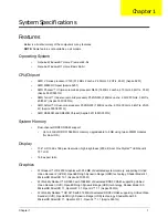
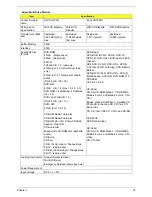
Right View
6
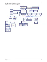
USB 2.0 ports
Connect to USB 2.0 devices (e.g. USB mouse,
USB camera).
7
Microphone-in
jack
Accepts input from external microphones.
Headphones/
speaker/line-out
jack
Connects to audio line-out devices
(e.g. speakers, headphones).
No.
Icon
Item
Description
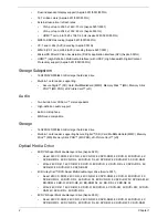
1
USB 2.0 ports
Connect to USB 2.0 devices (e.g. USB mouse, USB
camera).
2
Optical drive
Internal optical drive; accepts CDs or DVDs.
3
Optical disk access
indicator
Lights up when the optical drive is active.
4
Optical drive eject
button
Ejects the optical disk from the drive.
5
Emergency eject hole
Ejects the optical drive tray when the computer is
turned off.
Note:
Insert a paper clip into the emergency eject
hole to eject the optical drive tray when the computer
is off.
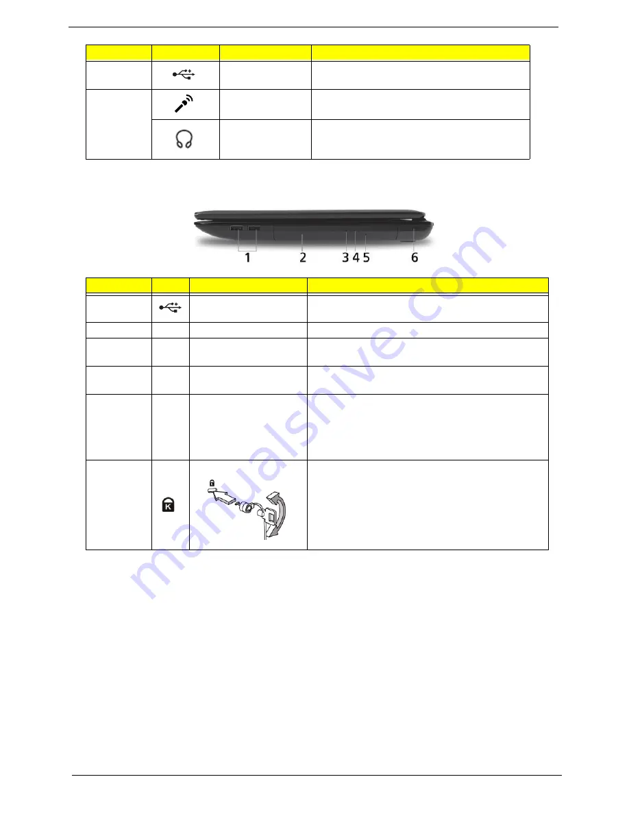
6
Kensington lock slot
Connects to a Kensington-compatible computer
security lock.
Note:
Wrap the computer security lock cable around
an immovable object such as a table or handle of a
locked drawer. Insert the lock into the notch and turn
the key to secure the lock. Some keyless models are
also available.
No.
Icon
Item
Description
Summary of Contents for ASPIRE 5251
Page 6: ...VI...
Page 10: ...X Table of Contents...
Page 34: ...24 Chapter 1...
Page 52: ...42 Chapter 2...
Page 76: ...66 Chapter 3 5 Lift the Speaker clear of the Upper Cover...
Page 78: ...68 Chapter 3 5 Lift the Right Speaker Module clear of the device...
Page 84: ...74 Chapter 3 5 Lift the USB board clear of the device...
Page 90: ...80 Chapter 3 11 Disconnect the Bluetooth to mainboard cable...
Page 92: ...82 Chapter 3 4 Carefully lift the Thermal Module clear of the Mainboard...
Page 103: ...Chapter 3 93 7 Disconnect the LVDS cable from the panel...
Page 105: ...Chapter 3 95 5 Lift the microphone set and cable clear of the LCD cover...
Page 121: ...Chapter 3 111 5 Connect the fan cable...
Page 124: ...114 Chapter 3 6 Connect the LVDS cable to the mainboard 7 Connect the microphone cable...
Page 127: ...Chapter 3 117 4 Connect the USB cable to the mainboard and lock the connector...
Page 130: ...120 Chapter 3 4 Replace the FFC and press down as indicated to secure it to the Upper Cover...
Page 146: ...136 Chapter 3...
Page 175: ...Chapter 6 165 Aspire 5251 5551G 5551 FRU List...
Page 176: ...166 Chapter 6 Screw List...
Page 177: ...Chapter 6 167...
Page 206: ...196 Appendix C...
Page 210: ...200...


