


154
Chapter 4
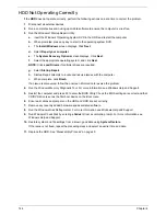
S3 Functions POST Code Table
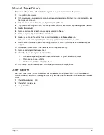
ACPI Functions POST Code Table
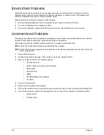
SMM Functions POST Code Table
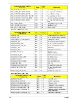
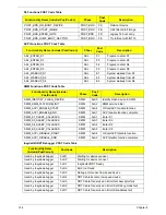
InsydeH2ODDT Debugger POST Code Table
Functionality Name (Include\ PostCode.h)
Phase
Post
Code
Description
POST_BDS_NO_BOOT_DEVICE
POST_BDS
F9
No Boot Device
POST_BDS_START_IMAGE
POST_BDS
FB
UEFI Boot Start Image
POST_BDS_ENTER_INT19
POST_BDS
FD
Legacy 16 boot entry
POST_BDS_JUMP_BOOT_SECTOR
POST_BDS
FE
Try to Boot with INT 19
Functionality Name (Include\ PostCode.h)
Phase
Post
Code
Description
ASL_ENTER_S1
ASL
51
Prepare to enter S1
ASL_ENTER_S3
ASL
53
Prepare to enter S3
ASL_ENTER_S4
ASL
54
Prepare to enter S4
ASL_ENTER_S5
ASL
55
Prepare to enter S5
ASL_WAKEUP_S1
ASL
E1
System wakeup from S1
ASL_WAKEUP_S3
ASL
E3
System wakeup from S3
ASL_WAKEUP_S4
ASL
E4
System wakeup from S4
Functionality Name (Include\
PostCode.h)
Phase
Post
Code
Description
SMM_IDENTIFY_FLASH_DEVICE
SMM
0xA0
Identify Flash device in SMM
SMM_SMM_PLATFORM_INIT
SMM
0xA2
SMM service initial
SMM_ACPI_ENABLE_START
SMM
0xA6
OS call ACPI enable function
SMM_ACPI_ENABLE_END
SMM
0xA7
ACPI enable function complete
SMM_S1_SLEEP_CALLBACK
SMM
0xA1
Enter S1
SMM_S3_SLEEP_CALLBACK
SMM
0xA3
Enter S3
SMM_S4_SLEEP_CALLBACK
SMM
0xA4
Enter S4
SMM_S5_SLEEP_CALLBACK
SMM
0xA5
Enter S5
SMM_ACPI_DISABLE_START
SMM
0xA8
OS call ACPI disable function
SMM_ACPI_DISABLE_END
SMM
0xA9
ACPI disable function complete
Functionality Name
(Include\ PostCode.h)
PostCode
Description
Used by Insyde debugger
0x0D
Waiting for device connect
Used by Insyde debugger
0xD0
Waiting for device connect
Used by Insyde debugger
0xD1
InsydeH2ODDT Ready
Used by Insyde debugger
0xD2
EHCI not found
Used by Insyde debugger
0xD3
Debug port connect low speed device
Used by Insyde debugger
0xD4
DDT Cable become low speed device
Used by Insyde debugger
0xD5
DDT Cable Transmission Error (Get descriptor fail)
Used by Insyde debugger
0xD6
DDT Cable Transmission Error (Set Debug mode fail)
Used by Insyde debugger
0xD7
DDT Cable Transmission Error (Set address fail)
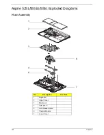
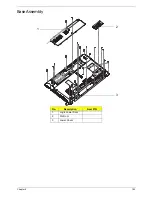
Summary of Contents for ASPIRE 5251
Page 6: ...VI...
Page 10: ...X Table of Contents...
Page 34: ...24 Chapter 1...
Page 52: ...42 Chapter 2...
Page 76: ...66 Chapter 3 5 Lift the Speaker clear of the Upper Cover...
Page 78: ...68 Chapter 3 5 Lift the Right Speaker Module clear of the device...
Page 84: ...74 Chapter 3 5 Lift the USB board clear of the device...
Page 90: ...80 Chapter 3 11 Disconnect the Bluetooth to mainboard cable...
Page 92: ...82 Chapter 3 4 Carefully lift the Thermal Module clear of the Mainboard...
Page 103: ...Chapter 3 93 7 Disconnect the LVDS cable from the panel...
Page 105: ...Chapter 3 95 5 Lift the microphone set and cable clear of the LCD cover...
Page 121: ...Chapter 3 111 5 Connect the fan cable...
Page 124: ...114 Chapter 3 6 Connect the LVDS cable to the mainboard 7 Connect the microphone cable...
Page 127: ...Chapter 3 117 4 Connect the USB cable to the mainboard and lock the connector...
Page 130: ...120 Chapter 3 4 Replace the FFC and press down as indicated to secure it to the Upper Cover...
Page 146: ...136 Chapter 3...
Page 175: ...Chapter 6 165 Aspire 5251 5551G 5551 FRU List...
Page 176: ...166 Chapter 6 Screw List...
Page 177: ...Chapter 6 167...
Page 206: ...196 Appendix C...
Page 210: ...200...


