


Chapter 3
109
Main Module Reassembly Procedure
Replacing the CPU
IMPORTANT:
Apply a suitable thermal grease and ensure all heat pads are in place before replacing the CPU.
The following thermal grease types are approved for use:
•
N-302 Dimand TIM Grease
•
Honeywell
IMPORTANT:
The CPU has a Pin1 locator that must be positioned corresponding to the marker on the CPU
socket.
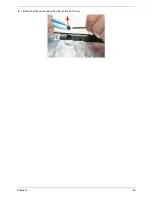
1.
Place the CPU into the CPU socket as shown, taking note of the Pin1 locator.
2.
Using a flat-bladed screw driver, rotate the CPU locking screw 180° clockwise to secure the CPU in place.
Socket
Pin1 Locator
Summary of Contents for ASPIRE 5251
Page 6: ...VI...
Page 10: ...X Table of Contents...
Page 34: ...24 Chapter 1...
Page 52: ...42 Chapter 2...
Page 76: ...66 Chapter 3 5 Lift the Speaker clear of the Upper Cover...
Page 78: ...68 Chapter 3 5 Lift the Right Speaker Module clear of the device...
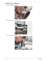
Page 84: ...74 Chapter 3 5 Lift the USB board clear of the device...
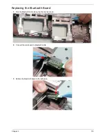
Page 90: ...80 Chapter 3 11 Disconnect the Bluetooth to mainboard cable...
Page 92: ...82 Chapter 3 4 Carefully lift the Thermal Module clear of the Mainboard...
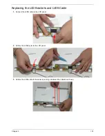
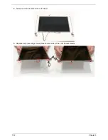
Page 103: ...Chapter 3 93 7 Disconnect the LVDS cable from the panel...
Page 105: ...Chapter 3 95 5 Lift the microphone set and cable clear of the LCD cover...
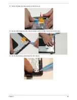
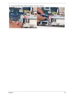
Page 121: ...Chapter 3 111 5 Connect the fan cable...
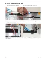
Page 124: ...114 Chapter 3 6 Connect the LVDS cable to the mainboard 7 Connect the microphone cable...
Page 127: ...Chapter 3 117 4 Connect the USB cable to the mainboard and lock the connector...
Page 130: ...120 Chapter 3 4 Replace the FFC and press down as indicated to secure it to the Upper Cover...
Page 146: ...136 Chapter 3...
Page 175: ...Chapter 6 165 Aspire 5251 5551G 5551 FRU List...
Page 176: ...166 Chapter 6 Screw List...
Page 177: ...Chapter 6 167...
Page 206: ...196 Appendix C...
Page 210: ...200...